STAY TUNED!
Subscribe to our newsletter and get the 600+ pages eBook Inside ARES:


Working With QUICK INPUT ARES Commander 2016 gives us information about the command that we are using directly at the pointer. At the same time, it offers us the coordinates of the position of the pointer. By clicking on a point, the Quick Input options appear. This is a new feature in ARES Commander that can be activated or deactivated here. When activated, contextual information appears about the angles and distance from the starting point. In this case, I can write a distance, for example. Then after pressing the TAB key, we can also change the angle, in this case adding degrees. Press ‘Enter’ to confirm the changes and to create the new point. Now we can let the polyline end perpendicular to this rectangular shape here. But when the pointer moves, we can see that many entity snaps appear. That’s why we should use the snap filter by combining
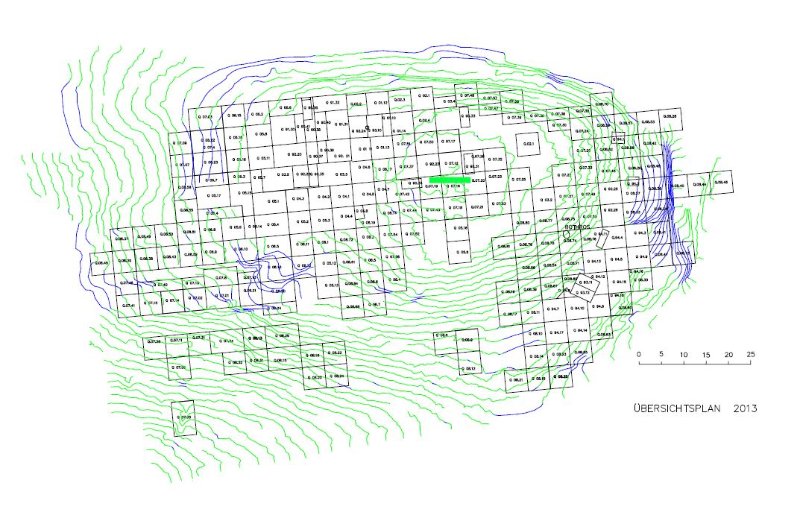
Architect and archaeologist Irene Blum works at the University of Bochum, Germany. She uses ARES Commander for excavation work in an antique city in Turkey. “As our activity goes on for many years at the same location but with changing staff, we need a user-friendly and versatile CAD program” Detailed Plans The ability of unlimited zooming in and out allows to create detailed plans of all the findings such as walls, components, fountains – everyone in the team has access and can see the area they are working on. “We feed ARES Commander with the coordinates we gain from surveying the site, so we can reproduce any point or line to scale – and also later identify where exactly this is on site”, says Blum. For this the various layers are a great help: Even the most diverse topics can be visualized individually or in any combination. This may be

Ares Commander 2015 presents “PowerTrim” Trim and extend CAD entities on the fly with the PowerTrim feature in ARESCommander. 0:00:08.720,0:00:15.200 ARES Commander 2015 presents “PowerTrim” to trim and extend better and faster 0:00:15.200,0:00:18.000 than in any other CAD software before. 0:00:18.120,0:00:19.980 Let’s see this example 0:00:20.040,0:00:23.280 Find the tool here in this drop down menu. 0:00:23.420,0:00:25.040 Click on the screen, 0:00:25.120,0:00:28.260 keep the button pressed and drag it. 0:00:29.040,0:00:33.480 This line lets you trim easily on the fly. 0:00:34.140,0:00:40.120 In addition, if we keep the SHIFT key pressed, TRIM turns into EXTEND. 0:00:40.560,0:00:43.660 So we can also extend easily. 0:00:44.460,0:00:50.340 In another example, select PowerTrim, click on the screen, keep the button pressed … 0:00:50.500,0:00:55.920 and drag to trim. Drop, and position the cursor somewhere else. 0:00:56.080,0:00:59.920 Press and drag with the mouse. 0:01:00.740,0:01:04.100 Keep SHIFT pressed to extend. 0:01:04.960,0:01:10.420 Finally, with PowerTrim, we can also clean corners. 0:01:18.640,0:01:20.100 Thanks for

Learn 3D Drawing Basics 1 00:00:09,660 –> 00:00:15,180 To create this part in 3D, we will simply need polylines. 2 00:00:15,980 –> 00:00:20,360 You will see in this video how they will be converted into three-dimensional elements 3 00:00:20,360 –> 00:00:23,820 with commands such as Extrude and Revolve. 4 00:00:24,260 –> 00:00:27,620 In this example, we can see several rectangles. 5 00:00:27,860 –> 00:00:31,439 A rectangle is a certain kind of a closed polyline. 6 00:00:31,600 –> 00:00:33,160 Here is one, 7 00:00:33,320 –> 00:00:34,460 here another … 8 00:00:34,580 –> 00:00:38,180 and here are more rectangles – in total we have six. 9 00:00:38,240 –> 00:00:40,160 Here we have a circle 10 00:00:41,680 –> 00:00:45,920 and on the other side we have two closed polylines. 11 00:00:47,20 –> 00:00:49,500 Let’s now create this part in 3D. 12 00:00:51,80 –> 00:00:55,300 We first work with this rectangle, whose corners should

Esri European User Conference 2015 October 14-16, 2015 Salzburg, Austria Learn more about Esri Events

Amit Kumar from CADblogbyamit talks about the new features of ARES Commander “Tons of new features in ARES Commander 2015 Service Pack 2, AREA command functionality developed to visualize selected area. Now you can see selected area in different color. Adding area and subtracting area will have a different color.” . Read the full article on CADBlogbyAmit
Amit Kumar talks about the ExplodeX Command in CADblogbyamit “With the ExplodeX command in ARES Commander, you can convert Ellipses and Splines into PolyLines. The command is useful to prepare drawings to export to other software programs that do not support Ellipses or Splines.” Read the full article on CADBlogbyamit here.
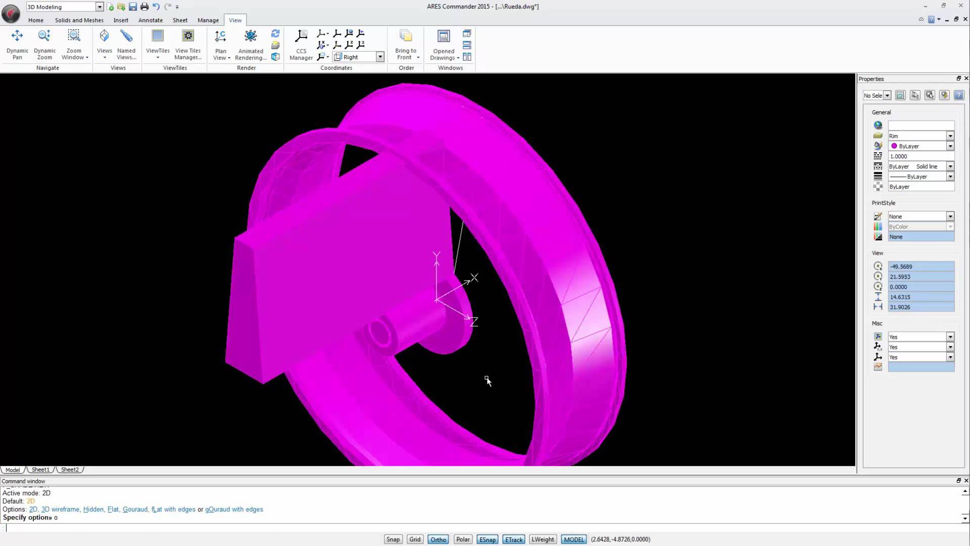
Watch the videos divided into 4 parts to learn more about 3D modeling in ARES Commander. Make changes to the external drawing 1 00:00:08,920 –> 00:00:10,720 We are working with this wooden bike 2 00:00:10,840 –> 00:00:14,420 which is not only a toy, but also a mechanical project. 3 00:00:14,580 –> 00:00:19,80 In previous videos, we saw how to create the saddle and its structure 4 00:00:19,280 –> 00:00:21,340 as well as wheels, 5 00:00:23,140 –> 00:00:26,380 frame, fork, and handlebar of this bike. 6 00:00:26,600 –> 00:00:30,620 The wheels are inserted in this drawing as external references. 7 00:00:30,700 –> 00:00:35,379 But the remaining parts of the bicycle are created directly in this drawing. 8 00:00:35,800 –> 00:00:42,80 To finalize the wheel we will open the wheel file to make the changes directly in this external drawing (XREF). 9 00:00:42,240 –> 00:00:47,720 As a result, the changes will appear
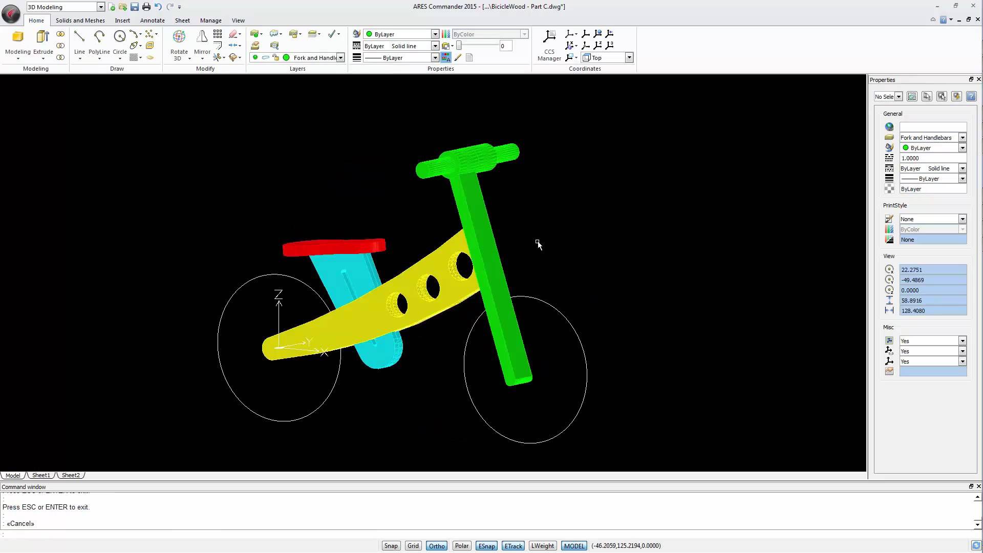
Watch the videos divided into 4 parts to learn more about 3D modeling in ARES Commander. Working with the Frame of 3D Model 1 00:00:09,340 –> 00:00:14,40 In this video we will create the frame and the fork of the wooden bicycle. 2 00:00:15,660 –> 00:00:22,360 To create this part of the structure we just need a closed polyline describing the outline of this shape. 3 00:00:22,700 –> 00:00:26,119 And then these circles to create the holes in it. 4 00:00:26,320 –> 00:00:31,160 The method we will use here is to redraw the outline of this figure. 5 00:00:31,880 –> 00:00:34,540 So, let’s select the polyline function. 6 00:00:35,180 –> 00:00:37,171 We can start here. 7 00:00:38,980 –> 00:00:42,199 In this case we need an arc in this section. 8 00:00:42,820 –> 00:00:46,420 For that we chose the option ARC with the “A” key 9 00:00:47,100 –> 00:00:49,380 and simply

Watch the videos divided into 4 parts to learn more about 3D modeling in ARES Commander. Create 3D Solids with the REVOLVE command 1 00:00:08,540 –> 00:00:13,719 In this video, we concentrate on the wheel. We will build it in 2 stages. 2 00:00:13,920 –> 00:00:19,800 This video is focused on the first stage, that is to say the design of the “rim” and the “tire” – 3 00:00:19,940 –> 00:00:23,180 two solids created with the command REVOLVE. 4 00:00:23,540 –> 00:00:28,480 To create these solids by revolution we need 2 closed polylines. 5 00:00:30,160 –> 00:00:34,20 One closed polyline will be used to create the rim 6 00:00:34,200 –> 00:00:37,50 and another one to create the tire. 7 00:00:37,120 –> 00:00:43,290 To create these polylines, we use the basic drawing and editing 2D commands. 8 00:00:43,290 –> 00:00:48,390 We start by creating a graphical reference – a rectangle. 9

Did you know that ARES Touch, our mobile DWG Viewer & Editor, is available for both Android and iOS?