Learn 3D Modeling and Design – Part 4
- 14/09/2015
- Posted by: Graebert
- Category: Tips & TricksVideos
Watch the videos divided into 4 parts to learn more about 3D modeling in ARES Commander.
Make changes to the external drawing
1
00:00:08,920 –> 00:00:10,720
We are working
with this wooden bike
2
00:00:10,840 –> 00:00:14,420
which is not only a toy, but
also a mechanical project.
3
00:00:14,580 –> 00:00:19,80
In previous videos, we saw how to create the saddle and its structure
4
00:00:19,280 –> 00:00:21,340
as well as wheels,
5
00:00:23,140 –> 00:00:26,380
frame, fork, and handlebar of this bike.
6
00:00:26,600 –> 00:00:30,620
The wheels are inserted in this drawing
as external references.
7
00:00:30,700 –> 00:00:35,379
But the remaining parts of the bicycle are
created directly in this drawing.
8
00:00:35,800 –> 00:00:42,80
To finalize the wheel we will open the wheel file to make the changes directly in this external drawing (XREF).
9
00:00:42,240 –> 00:00:47,720
As a result, the changes will appear in this
main drawing as they are inserted as XREF.
10
00:00:47,860 –> 00:00:51,220
Let’s open therefore the file containing the wheel.
Joining parts of the 3d model
11
00:00:52,40 –> 00:00:55,379
We start by drawing a circle
12
00:00:57,860 –> 00:01:03,300
which center is the center of the wheel and with a 2 cm radius.
13
00:01:05,400 –> 00:01:10,820
Next, we draw another circle with a radius of 0.5 cm
14
00:01:12,440 –> 00:01:15,980
and another one with a radius of 1 cm.
15
00:01:16,260 –> 00:01:18,680
Finally, we need a fourth circle.
16
00:01:18,880 –> 00:01:26,660
This time, we will use the OFFSET command to draw it parallel with a distance of 0.1 cm
17
00:01:28,420 –> 00:01:31,620
From this circle to the outside.
18
00:01:32,440 –> 00:01:35,120
Now let’s draw the spokes of this rim.
19
00:01:35,220 –> 00:01:41,20
For that, we will draw a line from this quadrant to somewhere inside the wheel.
Remove reference lines used for construction
20
00:01:43,500 –> 00:01:49,240
We use OFFSET to create lines with a 1 cm distance on each side.
21
00:01:52,500 –> 00:01:56,100
We extend the lines to the first circle.
22
00:01:58,200 –> 00:02:06,320
We further draw another line parallel with
a distance of 0.5 from the center line on both sides.
23
00:02:09,60 –> 00:02:14,680
Next, we select this line and use the grip to move its extremity like this.
24
00:02:14,900 –> 00:02:17,640
Let’s do the same on the other.
25
00:02:18,480 –> 00:02:22,820
Finally, remove the other lines that we used for construction.
26
00:02:24,160 –> 00:02:25,820
This will be our spoke,
27
00:02:25,920 –> 00:02:32,799
but in order to use it as a base for a 3D object, we need to convert it into a single closed polyline
28
00:02:33,80 –> 00:02:37,700
The circles are already closed polylines but we will need to convert the spoke
29
00:02:38,340 –> 00:02:42,120
As you can see we only have 2 lines here
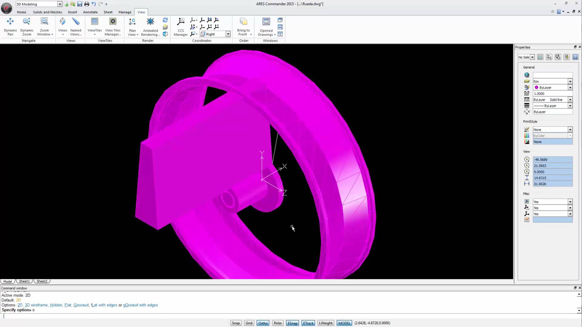
Isometric View of ‘Wheel’
30
00:02:43,000 –> 00:02:47,80
Let’s draw a polyline on top of the lines
we have drawn.
31
00:02:52,460 –> 00:02:54,520
We now have a closed figure.
32
00:02:54,680 –> 00:02:59,000
In our case, it doesn’t matter if it is partly inside the circle,
33
00:02:59,400 –> 00:03:01,620
at least for what we want to do.
34
00:03:01,980 –> 00:03:05,340
To begin with, let’s turn off the layer “Wheel”.
35
00:03:05,700 –> 00:03:08,619
When viewing the picture from an isometric view,
36
00:03:08,700 –> 00:03:14,000
we can see better the actual elevation of
the 2D elements we have created.
37
00:03:14,100 –> 00:03:18,739
In this case, they are in the XY plane with
Z equal to ZERO,
38
00:03:19,000 –> 00:03:21,800
which, if you don’t remember from previous videos,
39
00:03:21,940 –> 00:03:24,520
coincide with the axis of this wheel
40
00:03:24,700 –> 00:03:30,780
Let’s extrude the polyline, by a distance
equal to or greater than the width of the tire.
41
00:03:30,900 –> 00:03:33,900
We switch to a side view from the RIGHT
42
00:03:35,660 –> 00:03:38,859
We change the shading mode to 2D
43
00:03:39,560 –> 00:03:43,380
and we can see here how much it is extending beyond the rim.
44
00:03:43,620 –> 00:03:46,610
For the moment it doesn’t matter as we will cut it later,
45
00:03:46,740 –> 00:03:50,20
even if for the moment we have not defined how.
46
00:03:50,70 –> 00:03:51,900
So, for now we’ll leave it.
47
00:03:51,900 –> 00:03:54,40
We return to the isometric view.
48
00:03:54,40 –> 00:03:59,340
Now, let’s extrude the circles that are
as we know, in the center of the wheel
49
00:03:59,340 –> 00:04:02,20
and we will do it like this:
50
00:04:02,180 –> 00:04:09,960
The largest circle, we will extrude it with a negative value at least equal to or greater than the size of the rim.
51
00:04:10,340 –> 00:04:18,19
The following two circles, we are going to extrude them with a positive value of 3 drawing units.
Define a center position
52
00:04:19,899 –> 00:04:23,580
The smallest circle, we will move it
from the center of this shape
53
00:04:26,520 –> 00:04:28,940
to the center of this one.
54
00:04:32,100 –> 00:04:37,20
And from this position, we will extrude it
with a negative value,
55
00:04:38,360 –> 00:04:42,300
with a length even greater than the shape we created before.
56
00:04:43,580 –> 00:04:48,520
Now, we have here a cylinder, given that by extruding a circle you get a cylinder,
57
00:04:48,800 –> 00:04:51,700
assuming of course that the extrusion is straight
58
00:04:51,860 –> 00:04:53,880
And here we have another cylinder
59
00:04:54,240 –> 00:04:59,280
Let’s now perform a Subtraction between this cylinder and this one.
60
00:05:00,460 –> 00:05:04,140
The goal is to generate a hole inside the
largest cylinder.
61
00:05:04,340 –> 00:05:07,739
We have now a single cylinder but hollowed.
62
00:05:07,840 –> 00:05:11,450
We will see that better if we switch to another shading mode.
63
00:05:11,560 –> 00:05:13,840
For example, GOURAUD WITH EDGES.
GOURAUD WITH EDGES
64
00:05:14,100 –> 00:05:18,100
We see here the 3D solid object with a hole inside
65
00:05:18,260 –> 00:05:20,840
and inside this hole, the other cylinder.
66
00:05:20,880 –> 00:05:23,750
If we come back to the side view from the RIGHT,
67
00:05:23,800 –> 00:05:28,210
we will now cut the elements we extruded by the central plane
68
00:05:28,380 –> 00:05:33,260
But to begin with, you will remember that this cylinder was extruded backside.
69
00:05:33,440 –> 00:05:38,700
Therefore, this face is located in the middle plane of the rim and we will move it
70
00:05:39,700 –> 00:05:42,000
0.5 units to the left.
71
00:05:44,380 –> 00:05:48,649
Let’s switch to the 2D shading mode to see the hidden edges.
72
00:05:48,780 –> 00:05:51,299
Here you can see better the edges of this shape
73
00:05:51,379 –> 00:05:56,199
and what is the axis of the tire coinciding with the axis of the UCS
Use Slice command to remove the remaining parts
74
00:05:56,240 –> 00:06:00,830
Now we use the SLICE command to cut and remove the remaining parts.
75
00:06:00,830 –> 00:06:03,340
We selected these 2 entities
76
00:06:03,340 –> 00:06:08,159
The other one is not required because it is already ending on the cutting plane
77
00:06:08,460 –> 00:06:12,810
Press ENTER. We select this point because we know its position
78
00:06:12,879 –> 00:06:17,999
and a second one following the orthogonal direction to describe our cutting plane.
79
00:06:18,660 –> 00:06:22,80
With this axis, we have divided the figure
in 2
80
00:06:22,320 –> 00:06:25,640
and now we click on the side we want to remove.
81
00:06:26,160 –> 00:06:28,820
In our case, here on the right
82
00:06:28,990 –> 00:06:32,710
We switch to an isometric view, change the shading mode
83
00:06:32,860 –> 00:06:35,390
and see the expected result.
Check the 3d Model with Isometric View
84
00:06:35,400 –> 00:06:39,590
Now we will give life to the spoke of the rim, using a similar method.
85
00:06:39,590 –> 00:06:44,390
We go to the RIGHT side view and change the shading mode to 2D.
86
00:06:44,800 –> 00:06:48,240
We use the SLICE command again to cut this part
87
00:06:48,560 –> 00:06:55,240
But this time, the cutting axis will be indicated by a first point that should match the quadrant of the axes
88
00:06:55,420 –> 00:06:59,620
and another one located here in one extremity of the rim.
89
00:07:00,200 –> 00:07:02,880
We chose the side that we will be removed with a CLICK.
90
00:07:03,440 –> 00:07:06,60
And, back to an isometric view,
91
00:07:07,560 –> 00:07:12,560
we change the display mode and see our spoke that looks like one from a modern car.
92
00:07:14,320 –> 00:07:17,341
But we still have here, a part that should not exist.
93
00:07:17,480 –> 00:07:19,920
We will fix that also using SLICE
94
00:07:20,280 –> 00:07:25,419
Simply write the command, and after ENTER, select the figure, press ENTER
Indicate the points of cutting axis
95
00:07:25,580 –> 00:07:28,979
and indicate the points of the cutting axis.
96
00:07:32,960 –> 00:07:36,159
Now, let’s look at it from the FRONT view
97
00:07:36,640 –> 00:07:40,380
and we will replicate our spoke around the wheel.
98
00:07:41,000 –> 00:07:43,680
We can use the “PATTERN” command,
99
00:07:44,420 –> 00:07:47,240
in the dialog box, we choose “CIRCULAR”.
100
00:07:47,600 –> 00:07:50,219
We select the object we want to repeat.
101
00:07:50,669 –> 00:07:56,248
Next, we indicate the axis of rotation, that will be here in the center
102
00:07:56,440 –> 00:08:00,280
and set the number of copies we want, for example 7.
103
00:08:00,729 –> 00:08:02,748
Finally, click OK
104
00:08:03,000 –> 00:08:06,140
These spokes are independent elements, if desired.
105
00:08:06,500 –> 00:08:12,500
We could use the boolean operation UNION to unite them all together and unite them with the rim.
106
00:08:12,949 –> 00:08:18,169
Turn on the layer “Wheel” of the tire and have a look from an isometric view
107
00:08:18,169 –> 00:08:20,409
It looks great! Doesn’t it?
Perform Symmetry
108
00:08:20,480 –> 00:08:25,341
However, the spokes were created with an angle oriented to one side.
109
00:08:25,520 –> 00:08:32,380
If this was the rim of a car it would be fine, since the procedure is to create the same, or very similar.
110
00:08:32,480 –> 00:08:37,920
But when it comes to a bicycle wheel, you probably need a wheel looking the same on both sides
111
00:08:38,500 –> 00:08:43,100
Therefore, what we need to do now, is to switch to a side view.
112
00:08:43,360 –> 00:08:49,80
We need to copy the spokes and the axis we have on the one side, on the other side.
113
00:08:49,400 –> 00:08:52,300
Which basically means we will perform a symmetry.
114
00:08:52,700 –> 00:08:57,200
We switch off the layer Wheel and change the shading mode.
115
00:09:00,600 –> 00:09:03,60
Let’s use therefore the MIRROR command.
116
00:09:03,540 –> 00:09:07,319
We select the entities and define the axis.
117
00:09:15,580 –> 00:09:19,200
Now the rim is the same on both sides.
118
00:09:21,400 –> 00:09:24,620
Activate again the layer of the tire.
119
00:09:25,480 –> 00:09:28,220
And finally, we save the changes.
120
00:09:29,620 –> 00:09:35,460
Back to the main drawing, where the wheel was already inserted as an external reference,
121
00:09:35,680 –> 00:09:39,660
we see it is already updated with the new design
122
00:09:39,780 –> 00:09:46,800
This is a nice illustration of the 3D features you can find in ARES Commander from Graebert.
⇐ WATCH THE PREVIOUS VIDEO: CREATE A TOY – WITH 3D SOLIDS_PART 3
To learn more about ARES Commander, visit our Youtube Channel: GraebertTV