STAY TUNED!
Subscribe to our newsletter and get the 600+ pages eBook Inside ARES:

Learn how to make linetypes and linetype files with CAD Software ARES Commander. In this article, we will explain how to create line styles using an easy to use CAD program. When working on a CAD drawing, we need different line types or line type files also known as “line styles” in ARES Commander. Opening the LINE STYLE Dialog Box In the video above, for example, the circular viewport. Contains a line using a CONTINUOUS line style. We could change this to dots. It is also possible to load other types of line. For that, we can use the last option in the linestyle drop-down, which says ‘Other…’ or on the icon next to the linestyle drop-down menu . Both will take you to the LINE STYLE dialog box, where you can load the line types. Press LOAD, and note that several options appear. The line styles definitions are included in a filename with
ARES Commander allows us to create custom line types. In this video, we will learn to create a custom line style for CAD with a series of lines of different sizes. All of this in a very simple way. Line Types and Line Styles Line types in ARES are also known as “line styles”. Here, for example, we have a series of lines of different sizes, and we will create a line style with it. Our new line style pattern will start at this point and end at this other end. The vertical line is simply a reference element so that you can easily select the end point. The last space will be included in our line style. Now, from XTRATOOLS press the command MAKE LINESTYLE Define a name (without spaces) and add a description. After pressing OK, we have to select the start point and then indicate the end
Learn how to create Custom Linestyles in CAD Software ARES Commander easily. Custom Linestyes can be created either directly from a drawing pattern with the command MAKELINESTYLE, or the traditional way, with a text file ending in a .lin extension, (as shown in the video). Press LOAD, in the LINE STYLE dialog, and it will open a new dialog called LOAD LINESTYLES, which shows the contents of the .lin file. You’ll notice that it has a name and a description. Wondering how they are created? Simple, click on BROWSE and it directs you to the folder containing the file. You can see that the .LIN file has a simple structure when you open it using NOTEPAD (available in Windows). Be careful, any changes you make here will affect the .LIN file. In the video above, the file is called ‘MM.LIN’. The double M is short for millimeter, as it groups the line

1 00:00:08,860 –> 00:00:14,049 In this video we will see some of the tools that help you work faster with CAD layers 2 00:00:14,049 –> 00:00:15,480 in ARES Commander. 3 00:00:15,480 –> 00:00:20,640 For example, we can hide a layer, just by selecting an entity located on that 4 00:00:20,640 –> 00:00:21,640 layer. 5 00:00:21,640 –> 00:00:24,270 Or, activate all layers at once. 6 00:00:24,270 –> 00:00:28,680 We can even lock a layer, just by selecting an entity that belongs to 7 00:00:28,680 –> 00:00:29,680 it. 8 00:00:29,680 –> 00:00:35,300 Of course, we can also unlock layers by selecting one or more entities at a time. 9 00:00:35,300 –> 00:00:39,680 All of these Layer tools help us to work faster with layers in ARES Commander Isolate Layer Command 10 00:00:39,680 –> 00:00:42,740 One of my favorites is the Isolate Layer command 11 00:00:42,740 –> 00:00:47,000 that allows isolating the layer
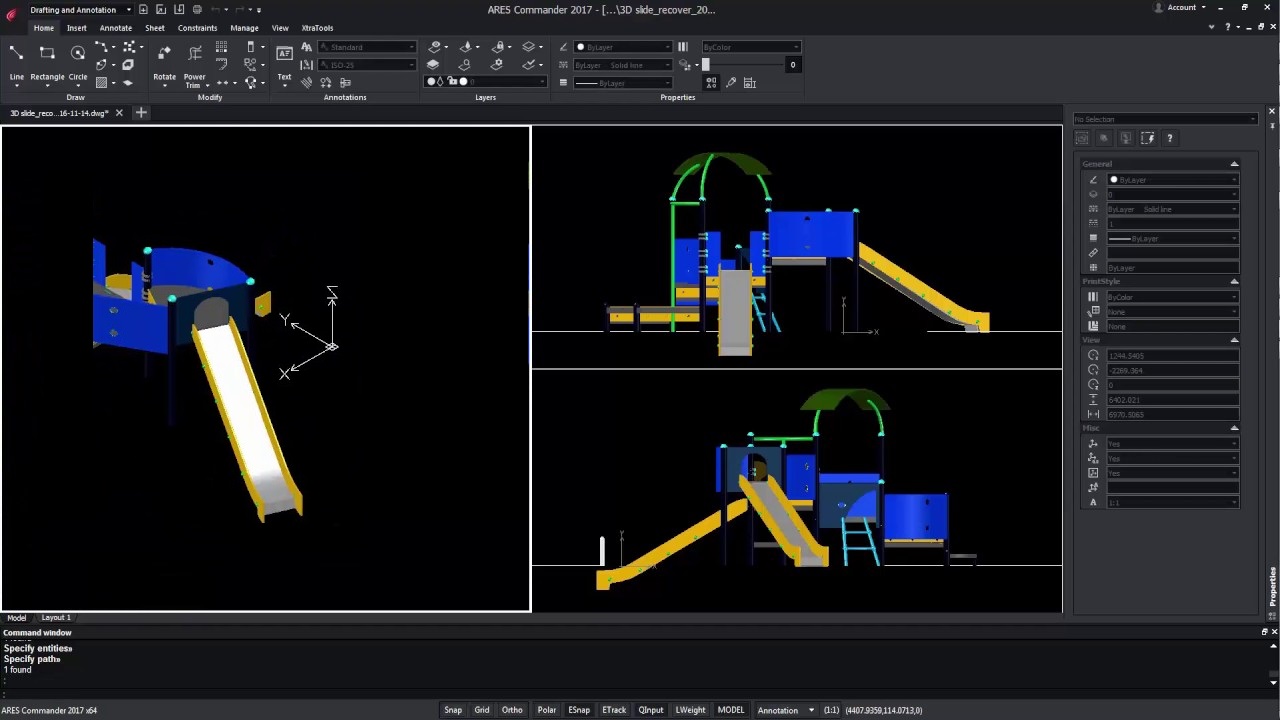
Amit Kumar writes about Path Pattern in ARES Commander The reasons Amit Kumar likes this feature is because users can: create a pattern or an uneven line decide the distance between the entities specify the entities count specify the distance and number for the entities set the settings for entity alignment set the orientation of the entities by tangent direction Read the full article on CADblogbyAmit Watch the video below to better understand Path Pattern in ARES Commander: Download a trial version of ARES Commander now!

The following sections describe file name standards created by several industry groups: American Institute of Architects Construction Specifications Institute California Department of Transportation The following article is an abstract of the eBook ‘Best CAD Practices’ by Ralph Grabowski. Graebert is happy to share with you some of the experience accumulated by Ralph as a CAD expert and as compiled in his eBook for which the reference can be found at the bottom of the page. Feel free to share feedback in the comment section below. AIA File Naming Convention The American Institute of Architects uses a file naming system based on its CAD Layer Guidelines (Chapter 3). You will see some similarities between the file and layer names, although layer names are more extensive. The AIA naming convention recognizes two types of CAD files: Model files contain the model drawn full size, but plotted to scale Sheet files hold non-model
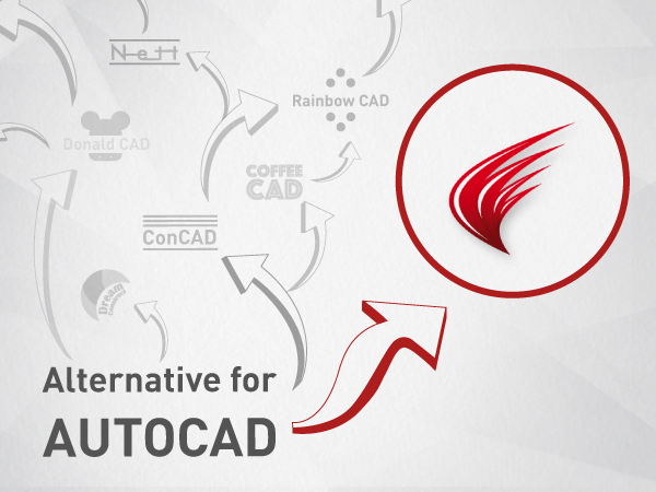
Essay: Seeking Alternatives to AutoCAD At the time this book was updated, Autodesk stopped selling permanent licenses to its software. Licenses are only available as subscriptions, which means that when firms cannot pay the fee each year, the software stops working. This is a scary thought for firms, especially during times of recession, and so there is a new interest in alternatives to AutoCAD. Here is the story from a competitor. The following article is an abstract of the eBook ‘Best CAD Practices’ by Ralph Grabowski. Graebert is happy to share with you some of the experience accumulated by Ralph as a CAD expert and as compiled in his eBook for which the reference can be found at the bottom of the page. Feel free to share feedback in the comment section below. I have over the last decade seen people’s reactions changing when considering CAD alternatives. I think this

Amit Kumar writes about Advanced PDF to DWG Conversion in ARES Commander ”The reason I like this feature is: 1. User can choose to maintain LineStyle as available in PDF 2. User can choose to maintain LineWeight as available in PDF 3. User can insert the drawing in the active layer, every content from PDF Drawing will appear in the active layer 4. User can use PDF Layer, all layers available in PDF will appear in the drawing.” Read the full article on CADblogbyamit

THE ROLE OF A CAD MANAGER As the manager in charge of computer-aided design (CAD), your role is to ensure the maximum efficiency of the CAD system — even though you may well be plagued daily by nit-picky problems, such as dry ink jet cartridges. The successful CAD manager is able to ease changes to CAD by carefully planning the process and keeping everyone informed. While the primary problem you will face is finding money for upgrades to the system, above all remember that your goal is to make it more efficient to get work done. When something makes the work more efficient, then implement it. The following article is an abstract of the eBook ‘Best CAD Practices’ by Ralph Grabowski. Graebert is happy to share with you some of the experience accumulated by Ralph as a CAD expert and as compiled in his eBook for which the reference can be

ARES® Map™ – bringing together the intelligence of GIS and A CAD system. Maps and floor plans created with ARES Map are saved natively in dwg but contain also smart GIS-enabled information associated with the entities. ARES Map is powered by ArcGIS® Online from Esri, the world leader for GIS technologies and also based on ARES Commander™, Graebert’s popular dwg-based CAD platform trusted by millions of professionals. The perfect CAD solution for GIS users A full DWG-based CAD software to create or modify any CAD drawing Unique tools to edit and convert CAD information into GIS-enabled entities Edit and synchronize your feature services with ArcGIS Online Add GIS intelligence to your CAD drawings Choose a coordinate system from hundreds of projected, geometric or vertical ones Work with map services and feature services from Esri servers or your own ArcGIS Online content Display and modify your GIS content directly from ARES
Did you know that ARES Touch, our mobile DWG Viewer & Editor, is available for both Android and iOS?