STAY TUNED!
Subscribe to our newsletter and get the 600+ pages eBook Inside ARES:
Insert Center Lines Insert Centerlines between pairs of lines, concentric arc and polyline segments Very popular for Mechanical design but also very helpful in other situations, the CENTERLINE command will draw a line at equidistance of the pair of entities you selected. The CENTER line style will be assigned by default and you can fine tune the extension of the Centerline. ARES Commander gives us the ability to quickly create a center line. We can choose 2 lines and ARES Commander draws a line that passes through its center. After selecting them we can know the properties of these lines, and determine a specific value of distance that will extend beyond the reference entities. Working with CENTERLINES In this case, we are going to relocate the center lines to match the sides of these tubes. Then we activate the possibility to set to a custom distance, choosing “YES” and typing a
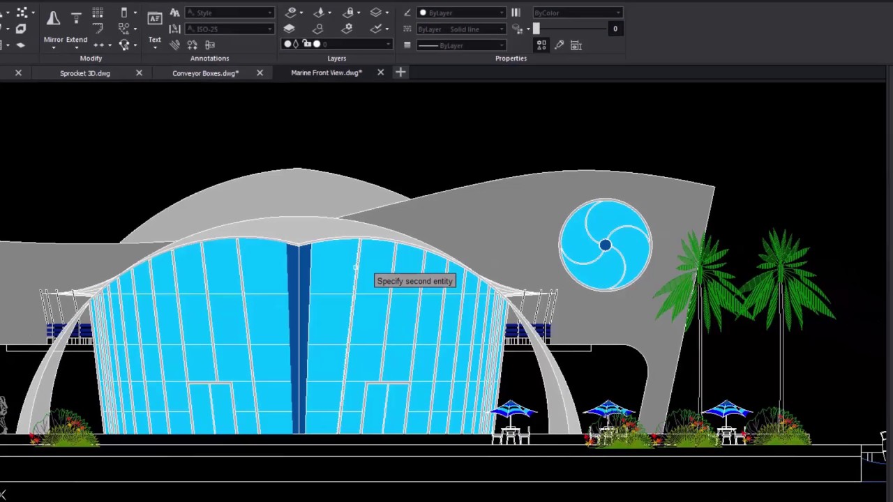
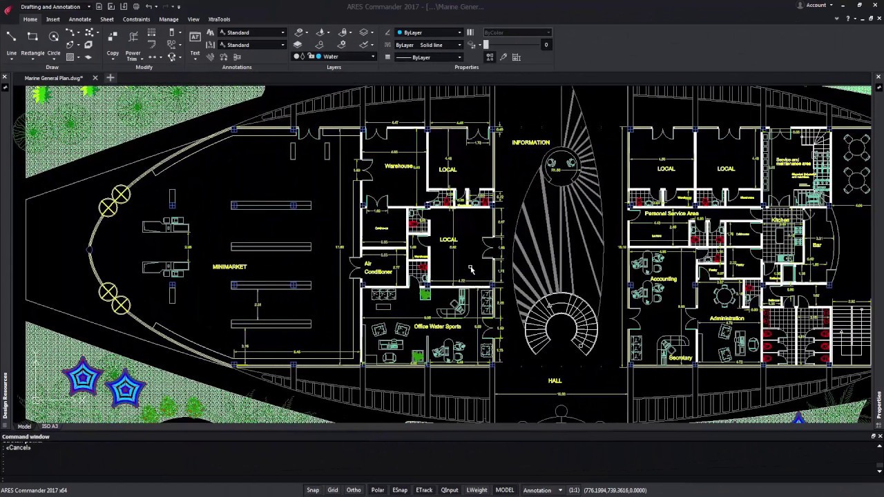
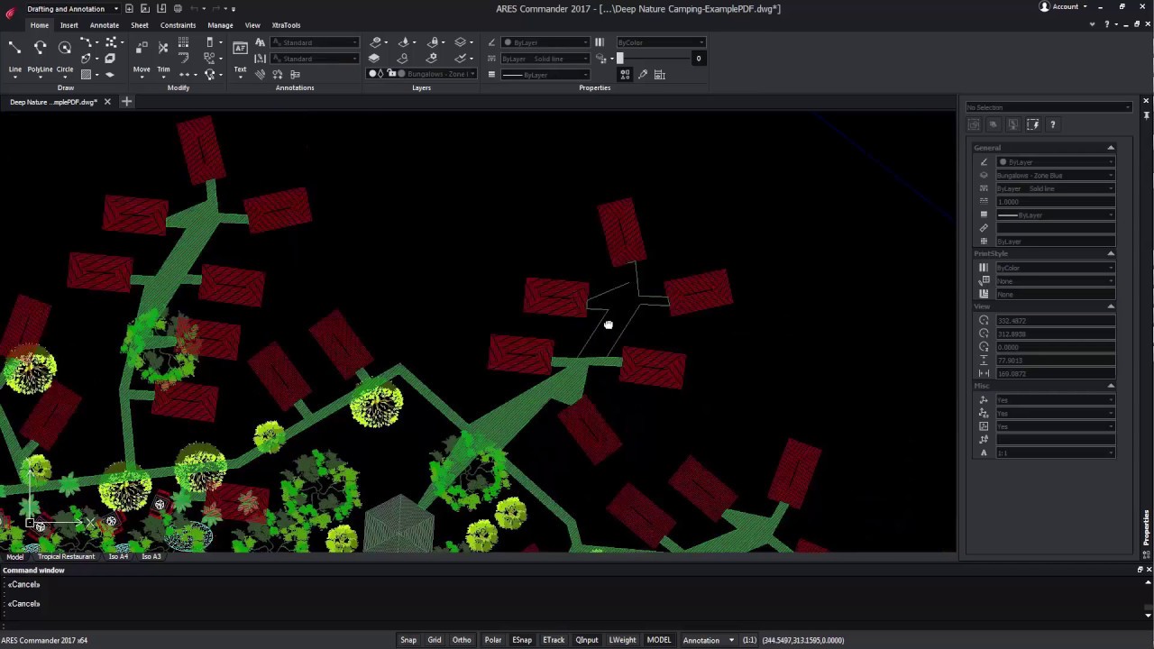
Advanced PDF to DWG conversion New features allow us to recover more information from the PDF Besides converting or batch-processing your PDF files into DWG files, ARES Commander offers now the option to recover the layers organization and names but also to maintain the LineStyle and LineWeight of entities. Recovering layers from a PDF file PDF is a very popular file format to share drawings. However, PDF cannot be modified. In ARES Commander you can use PDF Import to convert the PDF file to DWG entities. Now you can go even further and recover the layer structure from the PDF file. We can import the PDF and make all the entities that appear in the drawing grouped by color or group them according to the original layers. Grouping entities in a drawing Let’s see how it works, from the INSERT tab, choose PDF IMPORT. Select the desired file, choose one or
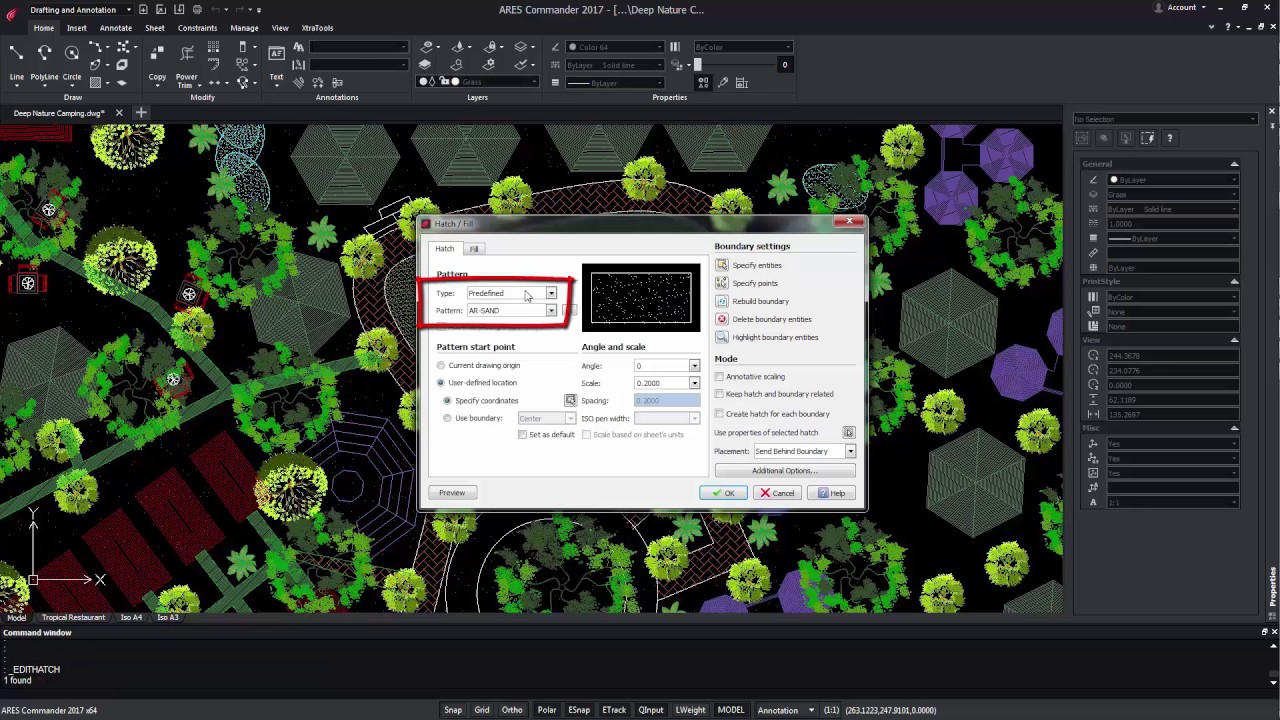
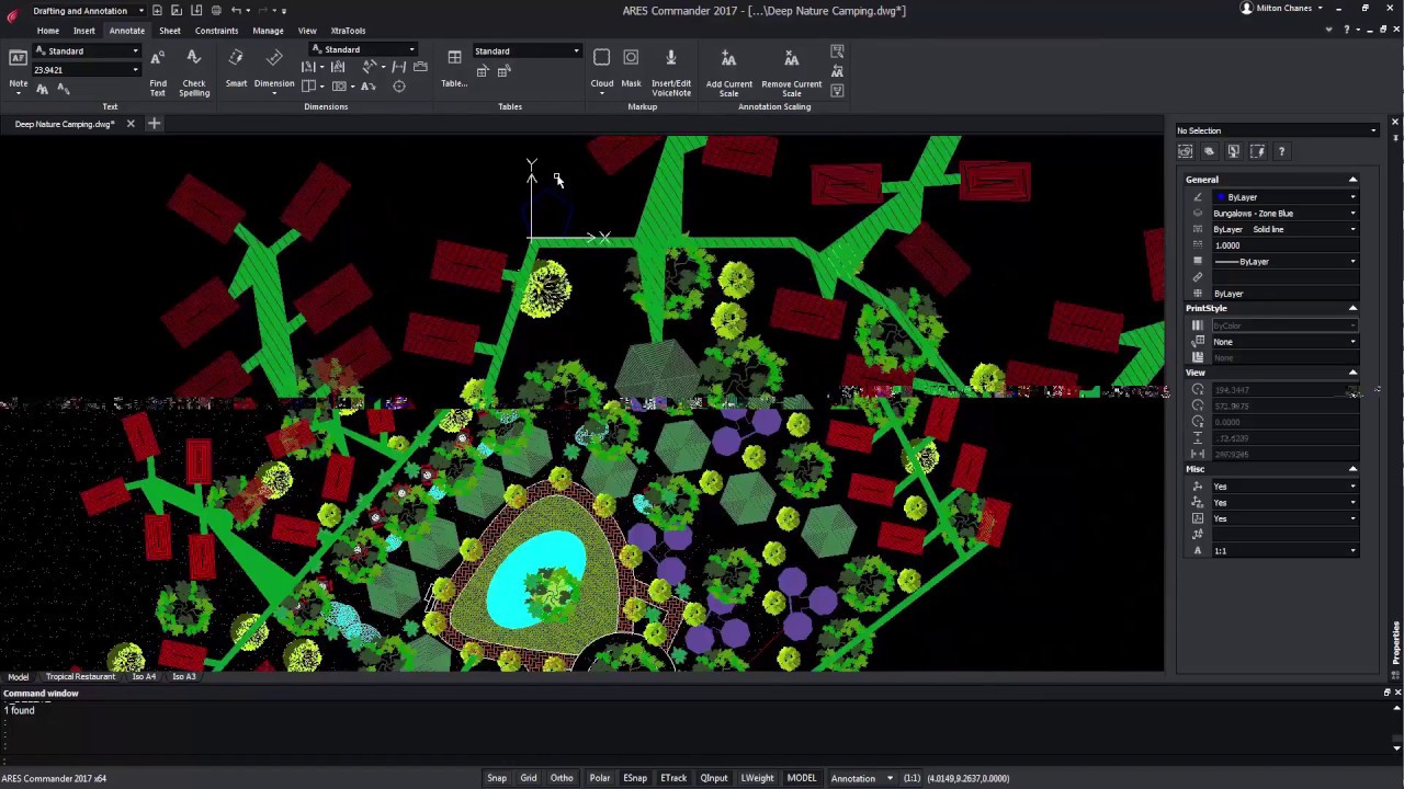
Trim and PowerTrim in Hatches and Gradients Unrivaled flexibility to edit the shape of your hatches and gradients You can now trim hatches and gradients with the TRIM and POWERTRIM commands. It’s never been easier to edit the shape of the areas containing hatches and gradients. Divided hatches and gradients maintain associativity and remain as one entity. ARES Commander offers the possibility to use TRIM with a hatch. For that, we only need a line, a polyline, an arc, etc., which serve as a cutting edge. Then select the TRIM command. Learning how to TRIM In this case, select the line, and after pressing OK select the side of the Hatch that we want to cut. Now, the POWERTRIM command also allows trimming the HATCH entities. To do this, select the command and press the pointer. By moving the pointer around the screen, ARES Commander will cut all the items
Relative Coordinates in Angles Use the “@” prefix to enter the angle from the last given segment You can now use the “@” prefix to enter relative angles just like you are already used to for relative distances. This unique ability simplifies significantly the coordinate input when you draw successive lines or polyline segments. ARES Commander is introducing in this version a small but innovative feature that can interestingly improve coordinates input. It is the possibility of adding polar coordinates with relative angles. Using the ”@” Command Let’s see how it works, In the video above, we are going to draw a pentagon with 5 equal sides of 5 meters and angles of 72 degrees. Obviously, we could have used the POLYGON command for that purpose but we just want to make a conceptual example to explain the new feature. Defining polar coordinates We start with a line and define
Multifunctional Grips Quick editing options appear when you fly over mid and end point grips Fly over entity grips and you will discover new contextual shortcut menus offering quick editing features that can vary based on the entity type: edit the length or stretch an entity from its end point grip, change the radius of an arc, insert a vertex on a polyline or convert an arc into a polyline. Working with Grips ARES Commander now gives us more options regarding the grips of entities. Grips are used to select the text and were available in the previous versions as well. It turns out that now, depending on the type of entity to be selected, we will have more variety of grips. In this dimension, for example, we could vary the position of the arrow by clicking on a grip. Positioning the pointer over a grip When positioning the pointer over
Polylines Editing Improvements Add vertex to midpoint, convert a segment to an arc or line and more New options in the command EDITPOLYLINE offer an increased productivity in the edition of polylines. You may convert an arc segment into a line and vice-versa, you may also add a vertex to the midpoint of a segment and change its position. Other new options include Taper and Reverse. ARES Commander offers new functions for editing polylines. Here we have a polyline composed of 2 segments. Among other things we can recognize it is a polyline from the aspect of the central grip. Selecting another entity When selecting another entity, the central grip is different, in this case, it is a square. This means it is a line. The central grip in lines can only be used to move them. Instead, by positioning the pointer over the central polyline grip, a contextual menu
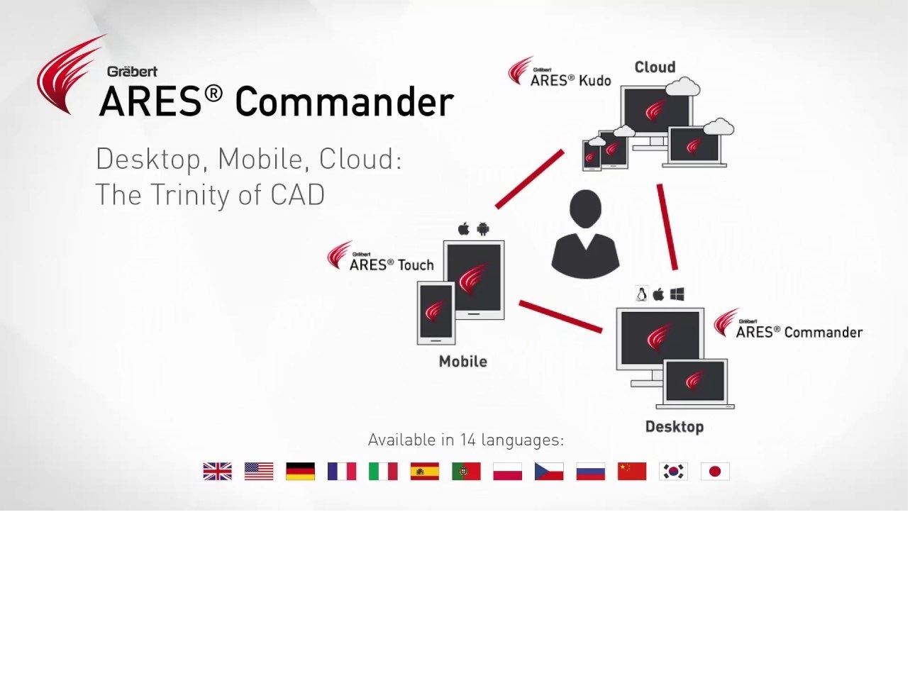
New “Trinity” Dark User Interface The new Dark UI is harmonizing the user interface across all the ARES CAD software and introducing new features The new Dark UI contributes to Graebert’s unique “Trinity” concept offering a seamless user experience across desktop, mobile, and cloud. Besides the fresh and modern look and feel you will enjoy enhancements such as auto-hiding palettes, command line completion, history for undo-redo and a welcome screen. The new ARES Commander is introducing a new user interface called the Dark UI. This Dark UI is not only giving a fresh and modern look to ARES Commander. It is also harmonizing the user interface across all the ARES CAD software to offer a smooth experience across desktop, mobile, and cloud. Indeed the same dark UI is used in ARES Touch for Android tablets and smartphones but also in the new iOS version for iPads and iPhones and the

Customer portal to manage licenses and devices Use your license on any computer and enjoy maximum flexibility The new Customer Portal facilitates the management of your licenses and subscriptions. You can also use your license to work from any computer. Indeed the same user can activate his license on up to two computers simultaneously and log out at any time to use his license on other computers. ARES Commander allows you to easily manage your license and share it with several computers. Note that the same user can be connected to the same account in up to 2 computers simultaneously. If you need to work from a third device, you can also just log out from one of the two other computers. For that, you can either log out from the program, or you can release the license from the Graebert Customer Portal. For ARES Touch – on your smartphones

In technical drawings dimensions are directly dependent on a dimension style that we can configure and customize. In this video tutorial, we show you how to get started with dimension styles creation. Create Dimensions 1 00:00:00,000 –> 00:00:14,280 ARES Commander provides all necessary 2 00:00:11,670 –> 00:00:17,310 tools to correctly create dimensions for 3 00:00:14,280 –> 00:00:19,830 technical drawings, the dimensions are 4 00:00:17,310 –> 00:00:22,859 directly dependent on a dimension style 5 00:00:19,830 –> 00:00:24,570 that we can configure and customize in 6 00:00:22,859 –> 00:00:27,480 this video we will learn what those 7 00:00:24,570 –> 00:00:29,698 characteristics are to access the 8 00:00:27,480 –> 00:00:32,759 dimension styles we need to click here 9 00:00:29,699 –> 00:00:37,970 on the icon dimension style, we can also 10 00:00:32,759 –> 00:00:40,250 find them in the annotate tab Modify dimension style 11 00:00:37,970 –> 00:00:43,370 this section contains options to modify 12
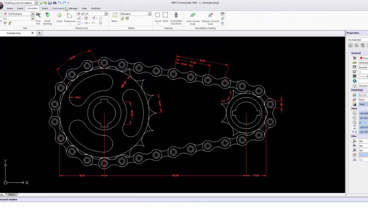
Learn all about dimension styles in here 1 00:00:09,350 –> 00:00:14,809 ARES commander provides all necessary tools to correctly create dimensions for 2 00:00:14,810 –> 00:00:17,380 a technical drawing 3 00:00:17,380 –> 00:00:22,538 find these tools and the section annotation in the Home tab or in the 4 00:00:22,539 –> 00:00:25,380 annotate tab 5 00:00:25,380 –> 00:00:30,960 these tools are easy-to-use they are very intuitive for example you can 6 00:00:30,960 –> 00:00:37,170 easily create lines parallel dimensions as well as narrow angles diameters radii 7 00:00:37,170 –> 00:00:38,640 etc 8 00:00:38,640 –> 00:00:44,100 in this tutorial series we teach you how to create and save dimension styles in 9 00:00:44,100 –> 00:00:47,790 addition to using a different standard and annotated of styles 10 00:00:49,120 –> 00:00:53,349 as we can see in this example the drawing is shown at different scales 11 00:00:53,350 –> 00:00:59,260 while the graphical appearance of the
Did you know that ARES Touch, our mobile DWG Viewer & Editor, is available for both Android and iOS?