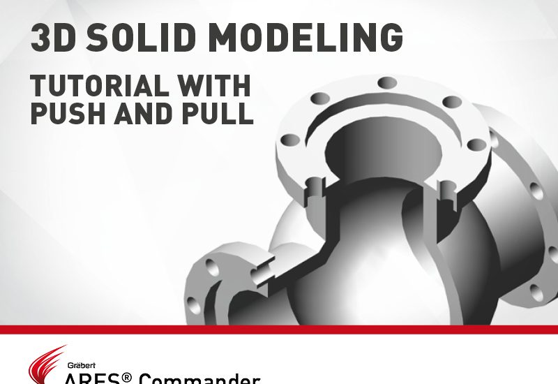
3D Solid Modeling Tutorial with Push And Pull
- 09/05/2019
- Posted by: Graebert
- Category: Tips & TricksVideos
In this video, we will see in action the command Push and Pull of ARES Commander, as well as other functions to model this 3D drawing.
Let’s start by creating a series of circles whose centre will be the absolute zero of the drawing.
Now we draw another circle, located in the upper quadrant of the central circle. We move it to its final position. Now we are going to copy it around this way using the Pattern command.
We select the circle. We indicate the number of copies and press ok. This is the way we are going to start working. Until now, with ARES commander we could create this form and 3D solids from them using commands like Extrude and Boolean Operations.
However, ARES Commander 2019 offers us the possibility of using the Push and Pull command that will allow us to create solids in a much simpler way. For that, we are going to move to the “3D Modeling” workspace.
We change to an Isometric view. Now, with Push and Pull … we can select an entity, positioning the pointer over it and By clicking IT we will get the equivalent of an extrusion.
In turn, with the same command, but positioning the pointer inside 2 closed forms or more than one as in this case, and ARES Commander will generate a 3D solid taking into account the closed interior shapes as hollows of the closed exterior form.
In short, as if we had combined Extrude with the Boolean Subtract operation. Pay attention that we can also select this solid and drag it from one of its grips, to observe that the 2D entities that gave rise to this solid continue to exist.
Let’s go back Only now we are going to extrude it using Push and Pull a distance of 25 mm, while the inner zone is going to be extruded in negative, also using Push and Pull, with a negative value.
Note that while the pointer is in a “positive” position, we can write “-” followed by the distance we need. Let’s go to another view, for instance, the one seen from the right. Now let’s move up this solid.
While drawing in the 3D workspace we can use the basic 2D commands we need such as move, copy, line, polyline, etc, from the keyboard, or the ribbon. But I will take the opportunity of this video to show you some alternative method to customize your work environment.
For that, we are going to do a right-click in the ribbon and from the drop-down menu, we go to MAIN where we choose to DRAW. This is first of all how you would show this toolbar with some useful commands. Similarly, we can add the Modify toolbar that contains move, copy and other similar commands.
Now we will use ARES Commander’s Tool Matrix palette. So we can drag the toolbars and lock them inside a side panel.
The most obvious advantage is that Tool Matrix, like a palette, can be placed anywhere on the screen. Also, if we choose the AUTOHIDE, it will remain hidden until we place the pointer on top; which allows us not to sacrifice our workspace.
We leave it on one of the sides to have it available when necessary. In this case to choose Move and thus move up the solid of higher height, until placing it within A FEW MILLIMETRES OF the other solid. Now, whatever it is, let’s make a series of copies. We copy the 2 elements at 150 mm distance.
Next, we select these entities and will rotate them 90º taking the absolute zero as the reference of rotation. Now we move it to the left 150 mm. Note we also need this shape on the opposite side. For this, we will use the Mirror. We switch to an Isometric view.
While we are close to the final form we lack a sphere in the center. Although it can not be any sphere since it must be hollow. To achieve this we need 2 spheres, one inside the other. Thus, with the Boolean Subtract operation, we can subtract the outer sphere minus the inside, and we will generate a hollow sphere.
We already have one. Now, before creating the next one, let’s go to a 2D wireframe view. Even better in a front view, to be able to see what happens inside. The sphere is currently intersecting with these cylinders. The truth is that the cylindrical shapes should reach the sphere and then disappear.
We can do a Boolean Subtract operation between one of the cylinders, and then we “remove” the shape of the sphere. This allows the cylinder to acquire the shape of the sphere. This is what we want to achieve.
Although it is true that we must reproduce this in the rest of the cylinders. Since the sphere is at the same distance from the rest of the cylinders, we could do a single Boolean operation.
In this case, we will show another way. For example, eliminating the lateral forms, and making a 45º symmetry of the one that is already corrected. Now another symmetry.
We see it from an Isometric view and let’s also change the Shading mode.
We need to create the sphere again. Only this time, we are going to draw a second sphere concentric to the previous one, with a smaller radius.
Now we have two spheres as expected. We switch to a wireframe view and next we use a Boolean “Subtract” operation between the outer sphere, to which we remove the inside.
We have achieved a hollow sphere, although we still cannot actually see it. To make it visible, we will use the Slice command that will allow us to cut a solid, as if it were a “knife”.
After indicating the cutting axis, we indicate the side we want to eliminate. As you can see, the sphere is hollow. Although we must correct the union with the tubes.
We go back, to eliminate the area of the sphere that should be hollow to connect with the tubes. For that, we are going to suffice with 2 solids of cylindrical shape, and we are going to do them in the following way.
From this position, we are going to draw a circle concentric to the sphere with a radius of 60 mm to which we are going to extrude it. The height will be, at least, the height of the sphere.
Now, from a Front view, we are going to copy the cylinder. We are going to turn it 180º to the new cylinder. Now we have to perform the Boolean Subtract operation. For that we select the sphere, and after pressing Enter, we select the first cylinder.
Now we change the shading mode, and also the point of view. Repeat the Boolean operation, to remove the other cylinder from the sphere. Observe how our piece has been defined.
Finally, from a top view, we will make a longitudinal cut using the Slice command. We define the axis through 2 points, and when making the cut, we indicate that we are going to stay with both sides, and that is why we write “B”. We are going to use the Slice command again, only this time we are going to make a cross-section of the half.
We define the cutting plane, and we click on the lower area to remove that area. We change to an Isometric point of view, in order to show our sectioned mechanical piece.
Learn more about the new tools of ARES Commander 2019 here.