STAY TUNED!
Subscribe to our newsletter and get the 600+ pages eBook Inside ARES:
Graebert has released a new version of its desktop CAD software solution: ARES Commander 2027. A full-featured, DWG-native application for...

PDF is a widely versatile file format, and one often used when sharing CAD drawings. However, the amount of information...

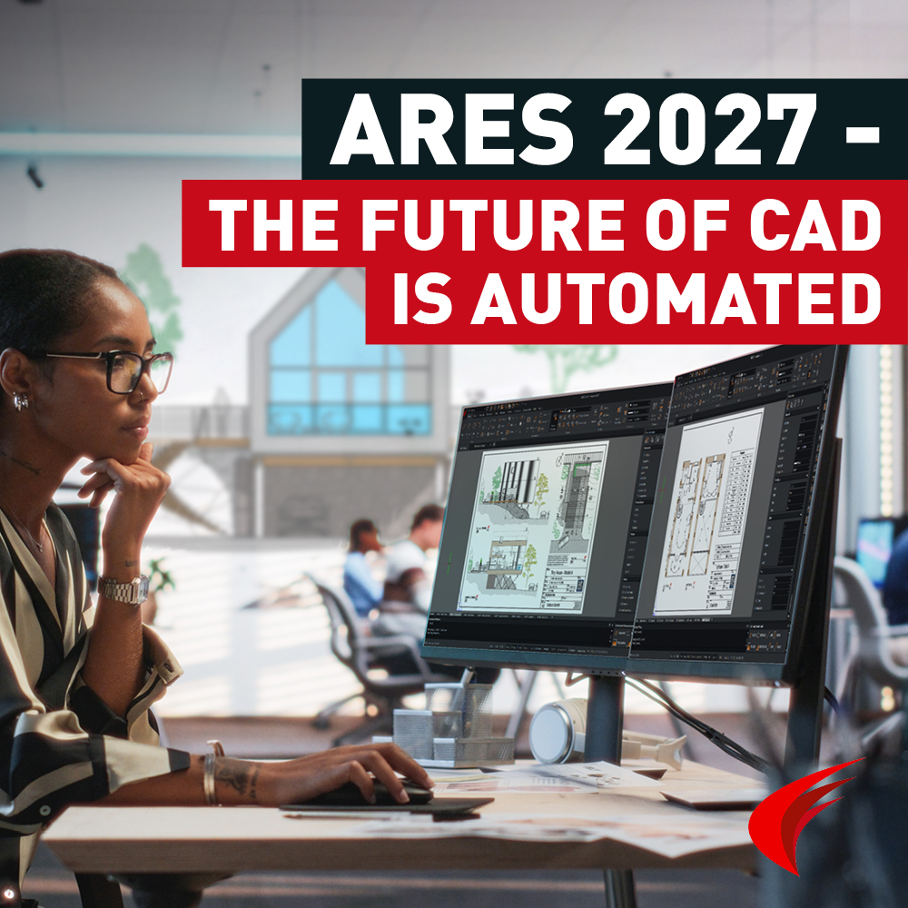
Graebert has officially launched ARES 2027, and this year’s release makes one thing very clear: the company is going all-in...

Do you want to learn more about technological trends brought forward by evolving technologies in the CAD industry in 2018? Editors of Cadalyst offer report the latest technology trends of 2018. Get a FREE guide with insights into the worlds of AEC and manufacturing by following this download link: https://info.cadalyst.com/1416-cadtrends2018 Jon Hirschtick, CEO of Onshape, believes that 2018 will be the “tipping point” for cloud-based CAD. “Different vendors have different interpretations of cloud CAD, but they all realize that most engineers will be moving the bulk of their work online over the next 5-10 years.” Cedric Desbordes, sales & marketing executive for Graebert, remarks “On the budget side, companies like to deploy such solutions to a larger audience to better share the technical knowledge, but in a cost-effective way. Ten years ago, the companies looking for alternatives to AutoCAD were mostly small- or medium-size firms. This is not true anymore, as

Amit Kumar writes about Split Dimension Tool in ARES Commander ‘The reasons I like this feature are: Improves readability of the drawing User can specify manual distance whenever required Entire drawing annotation can be handled Maintains dimension association with the entity User can refill the dimension gap by joining them Apparent intersections are also handled’ Read more on CADBlogbyAmit
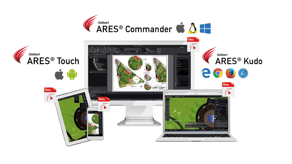
ARES Commander 2018 Much more than a cost-effective CAD Software for dwg editing, ARES Commander brings your productivity to the next level with smart productivity features and a unique concept: The Trinity of CAD™. The ARES Trinity of CAD Software combines the best of what each platform has to offer: Desktop, Mobile, and Cloud are combined into a unique user experience generating high synergies across all your devices. The highly flexible licensing of ARES Commander allows the same user to work from several computers under Windows®, MacOS® or Linux®. Each license includes also a 1-year renewable subscription for ARES Touch™ and ARES Kudo™. ARES Touch: The perfect companion for your mobile devices Subscribers of ARES Commander can enjoy ARES Touch on all their mobile devices at no additional cost. With more than 150 CAD features, ARES Touch is the most advanced Mobile CAD solution currently available for Android and iOS.

A pre-release version of ARES Commander 2018 can be downloaded here. It includes the following new commands and features: DWG 2018 File Format support: Release 2018 can read DWG files up to the latest version of this format (R2018) and can write such files up to the next to the latest version (R2013). The same applies to DXF (Drawing eXchange Format) files, which store the drawing database contents unencrypted. Some More New Commands and Features: Helix Creates 2D spirals and 3D helixes. Block commands Contains more tools for Blocks and BlockAttributes ◦ RedefineBasePoint. Sets new base points for Blocks. ◦ BlockAttributeManager. Manages properties and settings of BlockAttributes Block definitions. MultiLeader commands. Uses advanced leader creation and editing. ◦ MultiLeader. Creates MultiLeaders based on MultiLeaderStyles. ◦ EditMultiLeader. Adds and removes leader lines for MultiLeaders. ◦ MultiLeaderStyle. Creates and manages MultiLeaderStyles. ExportTable Exports tables in
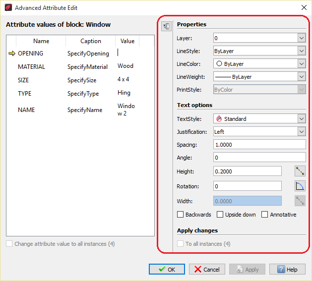
Amit Kumar writes about EditXAttribute in ARES Commander ‘The reasons I like this feature are: User can quickly change the attributes Information, as well as properties, can be changed Properties like Name, Height, Color and many other Editing the attributes are very easy We can update selected attributes with Value / Properties OR both. We can update all available attributes in a drawing.’ Read more on CADBlogbyAmit

Graebert Annual Meeting 2017 Key highlights of the Graebert Annual Meeting We had a lot of fun at the Annual Meeting and would like to share with you our recap video. In case you missed them you will also find below some interesting articles written after the event. A special thank you to our partners who joined us on stage for a keynote. Some articles by tech journalists following #Graebert17 ‘Regardless of how Autodesk perceives its competitors, it’s clear that Graebert has great confidence about the value of its products and its competitiveness going forward, and is eager for more visibility in the market.’ – Cyrena Respini-Irwin on Cadalyst Read more… ‘In this season when many CAD users are taking a close look at how they buy and manage their CAD technology, Graebert offers a unique technology proposition and a compelling value proposition.’ – Randall Newton, Consilia Vektor Read more…

Exploring The Layer Manager Technical drawings are characterized by using LAYERS. It’s easy to organize drawings using layers. In this video, we will learn how to create and configure layers in technical drawings. For that, we need to click on LAYER MANAGER. Then press NEW. Name the layer. Determine if that layer is going to be visible or not. If it will be blocked. Or assign a color. We can also determine the line type known in ARES as “line style”. Or you may also load a specific line style. Layers may have a line thickness configured. Note however that, at the time of printing, there is the possibility to use a print style to change these parameters. In such a way that we can keep the thickness of the drawing, or we can make a new configuration according to the colors. Layer Options A layer can be transparent or
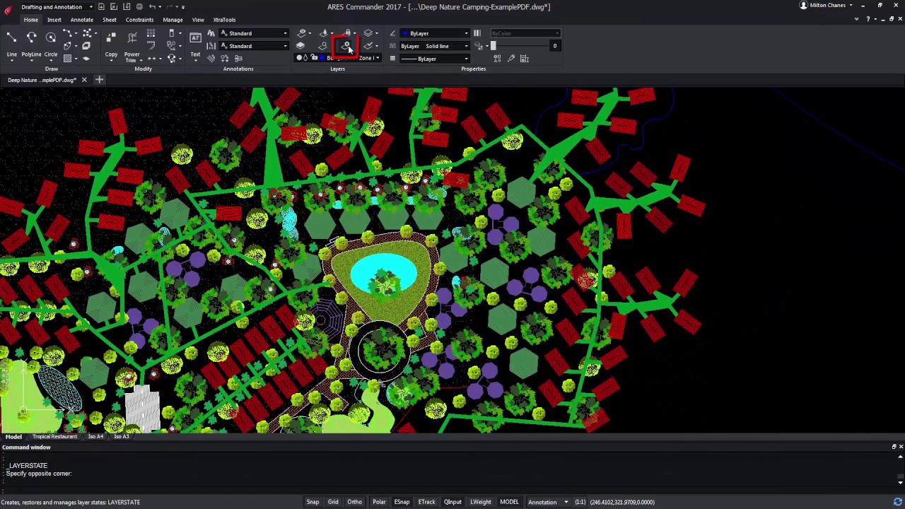
What Are Layer States in CAD Drawings? Working with a file with multiple layers can be time-consuming, especially if we frequently have to enable and disable multiple layers. Even if this drop-down menu is helping us. It is clear that, as we move forward in such a project, we will have to frequently activate and deactivate layers, or groups of layers. For example, to separate those that are related to nature, from others like the layers related to the buildings of this project. ARES Commander allows us to save the properties of the layers, in what is called “LAYER STATES”. From the LAYER STATES MANAGER box, we can create a new state with a custom name. Now, we edit the new layer state. In the edit dialog box, we will choose to make visible all layers related to vegetation. Hiding Layers We want the remaining layers to stay hidden. It

In this video, we will be sharing with you our Top five pieces of advice to work better and faster with CAD layers. Let’s begin a countdown starting with bottom-up… Number 5 Make sure to create a well-organized layer structure. They should be easy to group. For that purpose, we start with an “A” all the layers related to ANNOTATIONS. We could use “F” for layers related to furniture. “P” for PLAN, and some others like the “S” for STRUCTURE. We could even use the “X” for everything that has to do with the pages, title blocks, and frames in the layouts. Thus, by alphabetical order, it will become easier to find a layer within a specific group. Keeping this advice in mind, create a configuration of the layers you most frequently use and save them inside a custom DWT template. This way you will save time each time you start a new

Layer Preview in ARES Commander ARES Commander brings some interesting features that allow us to manipulate and organize layers with greater productivity. Highlighting among them is the command LAYER PREVIEW, which is exclusive to ARES Commander. This command allows us to select layers and visualize their contents and even select groups of layers. Navigate through the Layer Preview Command Select layers, and use the Zoom and Pan command to take a closer look. Press ESC to return to the dialog box. The “RESTORE LAYERS STATE WHEN EXIT” option, when it is active, determines if the previous layer state will be restored after closing the LAYER PREVIEW command. Pay attention, at this point, it says it will restore it. Press CLOSE and the drawing will return to the previous configuration. Layer Configuration with Layer Preview Now, let’s try the opposite. Select a group of layers, and deselect the box. Press CLOSE.
Did you know that ARES Touch, our mobile DWG Viewer & Editor, is available for both Android and iOS?