Discover the Top New Features
of the ARES Trinity of CAD Software

Easy Transition from AutoCAD®
The right CAD software can help you become much more productive,
but only if you understand how to use it.
ARES Commander isn’t just easy to use; it’s easy to learn, too. With its AI assistant and an updated yet familiar interface, making the switch from your old CAD program is simple.
New Start Tab and UI Configuration
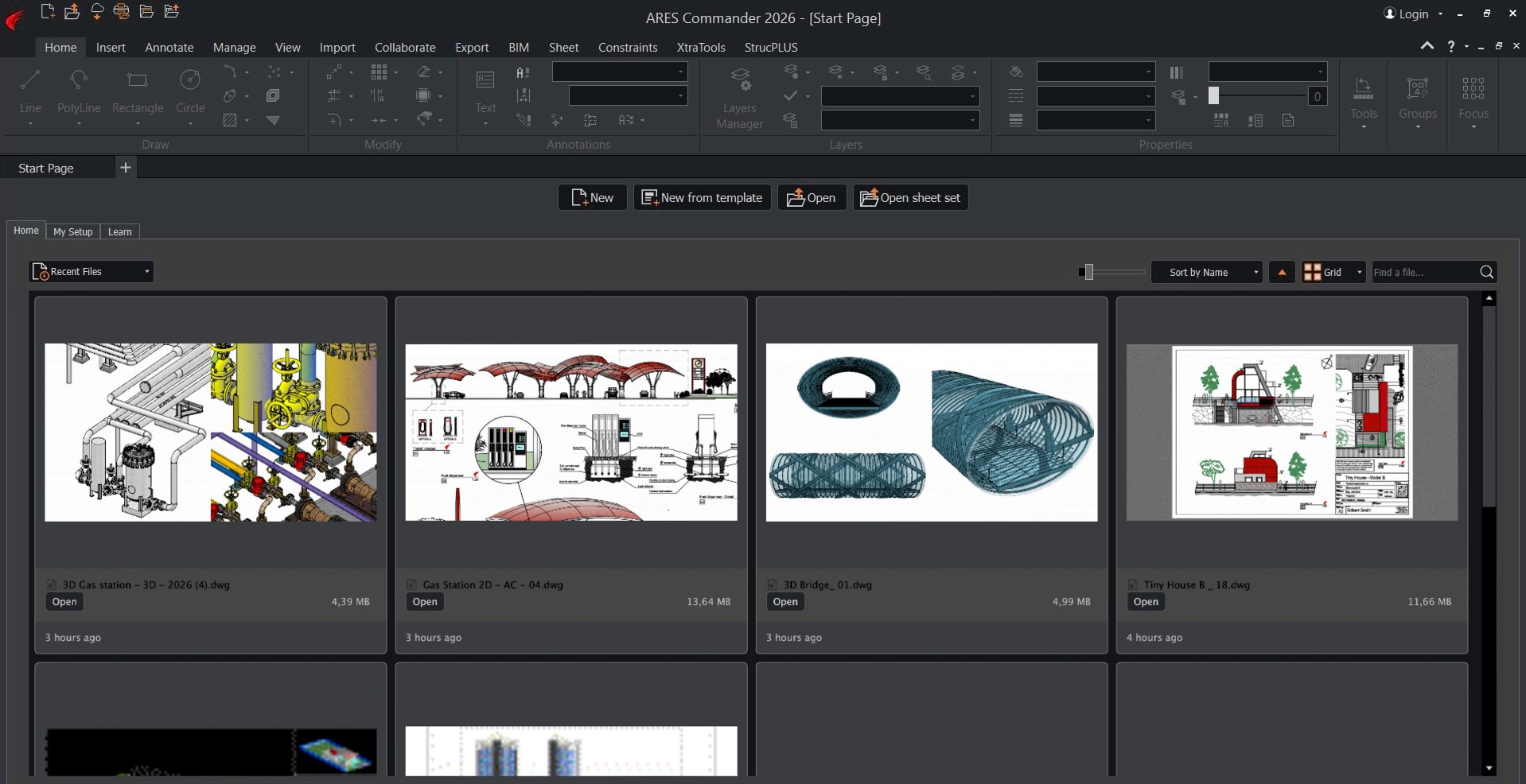
When users open ARES Commander, they will be greeted with a new way to begin their work each day. The new Start Tab centralizes key operations and creates a smoother user experience from the moment the application opens, replacing dialogs with a streamlined, welcoming interface.
Home: Quick Access Recent Files
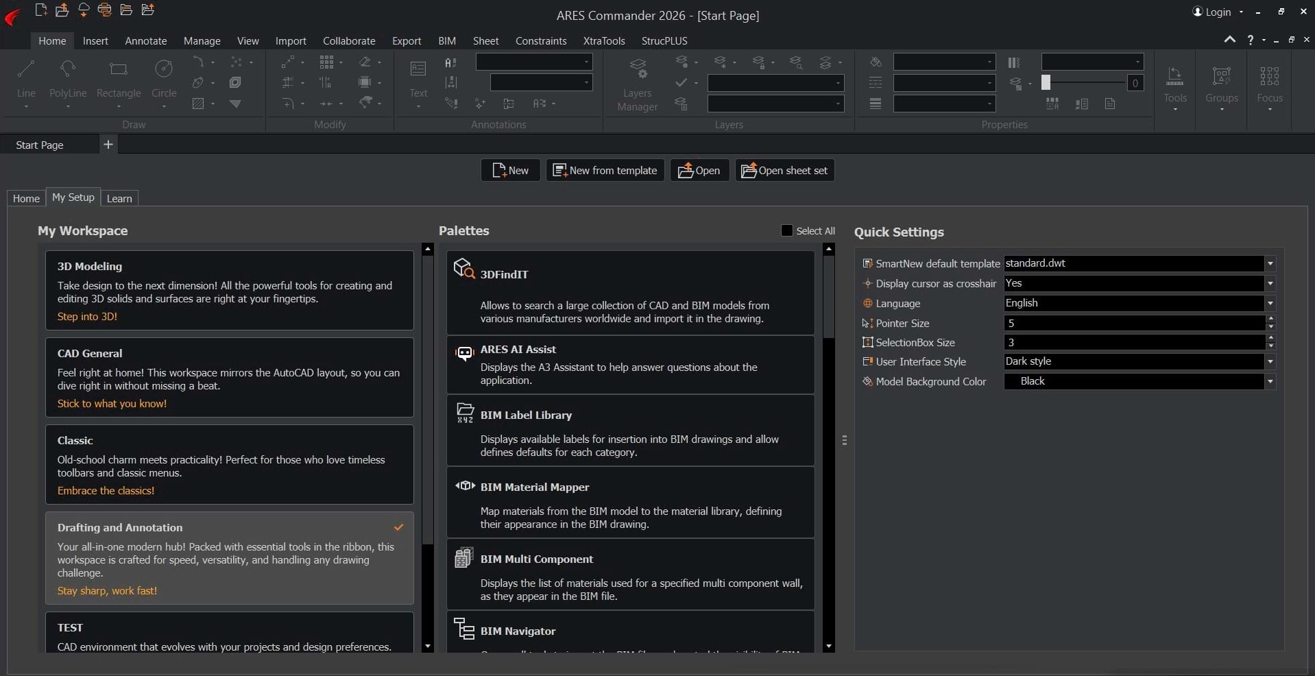
Setup: Organize UI Configuration
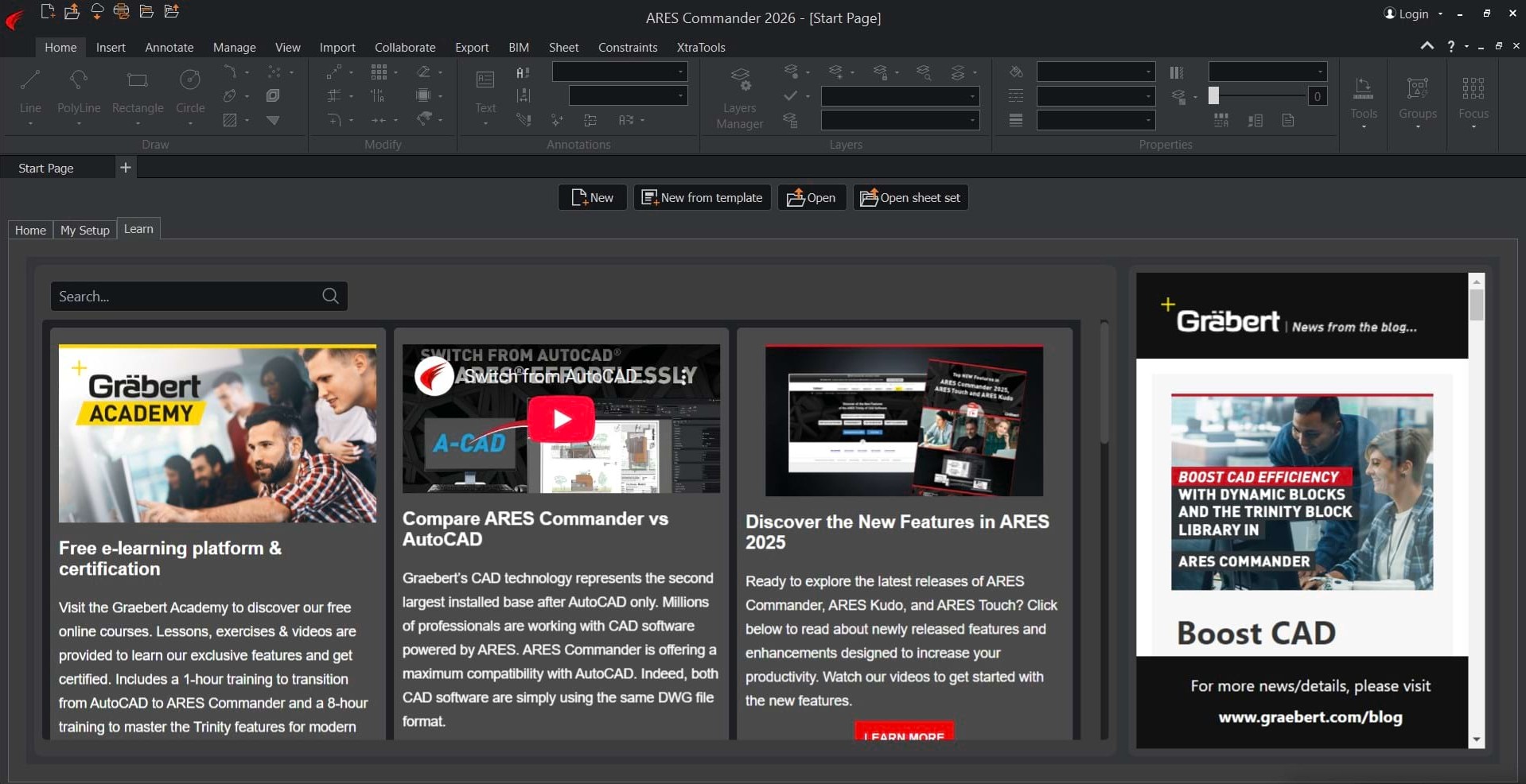
Learn: Access Learning Resources
Access educational resources and training at any time
Users of all kinds benefit from having tutorials, documentation, and skill-building resources freely accessible. This section provides access to videos, articles, and even the online Graebert Academy. The wide range of learning material supports both new users and experts alike, whether they’re troubleshooting an issue or searching for an advanced tool.
Smooth the transition from AutoCAD
New users transitioning from AutoCAD or similar CAD applications will quickly feel at home in ARES Commander when the workspace is configured just the way they like it. To simplify the process, a wizard helps with selecting palettes and other options. Additionally, the CAD General workspace is now enabled by default, providing a familiar environment from the start.
Start new drawings effortlessly
Users can access sample drawings or launch new projects instantly, selecting the appropriate units and scale for specific project types. This eliminates any project setup friction and ensures a productive start to each new drawing.
Customize workspace
The new Start tab provides quick access to workspace customization, allowing users to tailor the user interface according to personal preferences and project needs.
Quickly review recent projects and jump back in
A quick project review option helps users track recent work, encouraging continuous design improvement and making it easy to stay on top of evolving projects. Users can pick up their ongoing projects exactly where they left off, ensuring efficient, uninterrupted progress, whether working alone or as part of a team.
Additionally, the CAD General workspace — now enabled by default — provides a familiar environment for users transitioning from AutoCAD or similar CAD software.
Contextual Ribbons for Gradients and Pattern
Contextual ribbons provide users with tools that are relevant to their current selection in the drawing, thereby reducing the time spent searching for commands.
Gradients
Patterns
Pattern Editor
This smart tool presentation enhances productivity: Users can quickly access the most applicable options for each specific task, without wading through irrelevant features.
ARES Commander has added two new contextual ribbons to its tool set:
Gradients, which builds on the previously released Hatch contextual ribbon, and Pattern.
With their focused controls, these additions enable faster adjustments to gradient fills and pattern designs, making it easier to create visually appealing results.
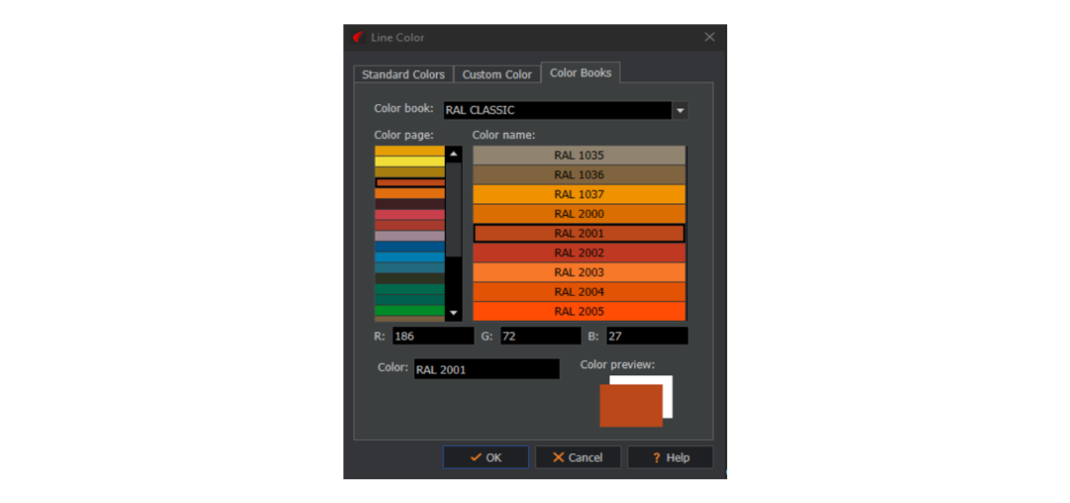
Custom color books (ACB files)
ARES Commander now supports custom color palettes, also known as color books, enabling users to access a wide range of standardized color palettes directly within their projects.
This feature is ideal for professionals who rely on precise color standards for branding, industry compliance, or consistent representation of materials.
With color books, users can quickly select and apply exact shades from popular color systems such as those from Pantone and RAL, ensuring visual accuracy and consistency across designs.
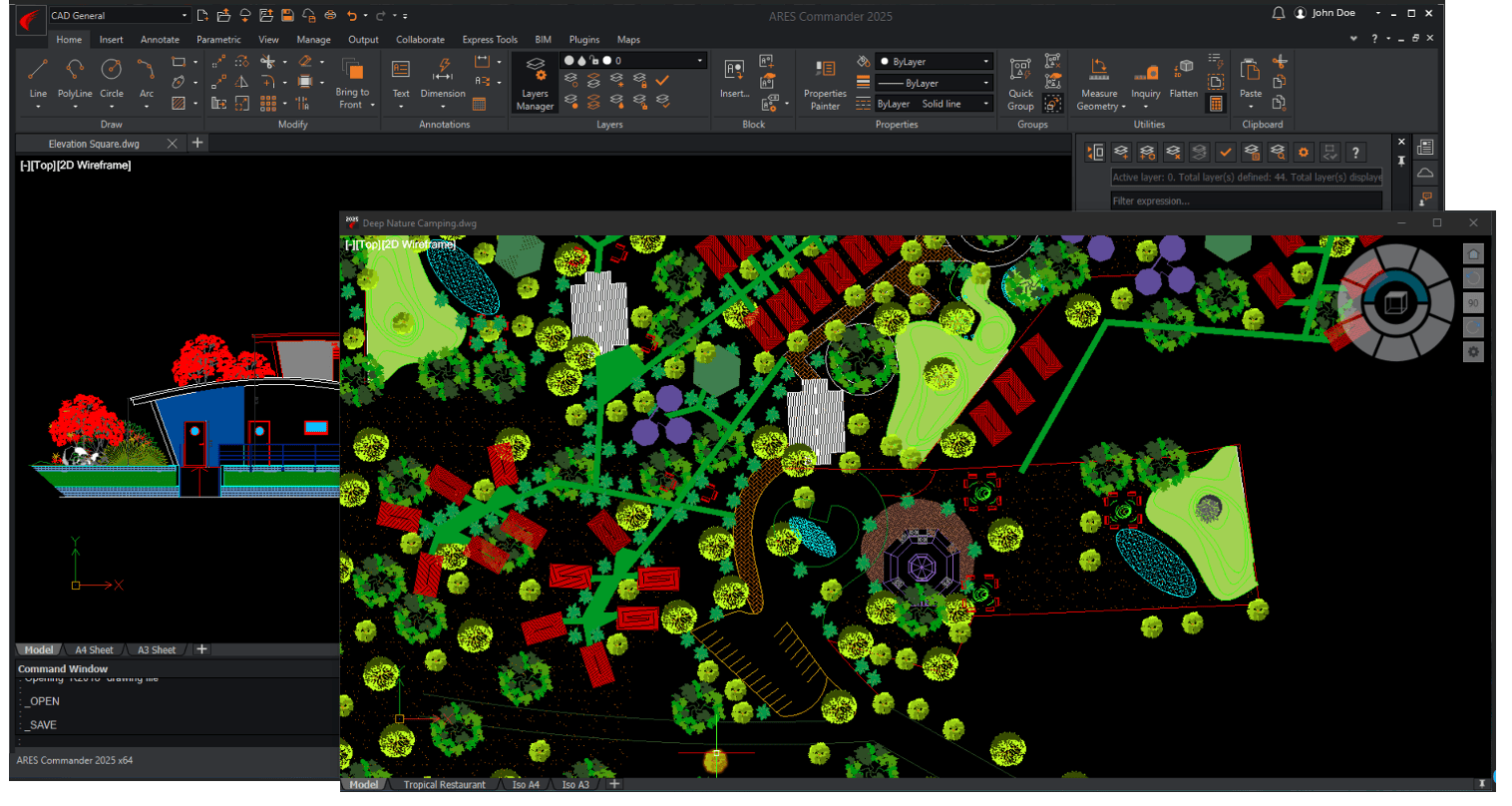
Open drawings in floating windows
The new floating document window feature in ARES Commander allows users to open drawings in separate windows outside the main application.
This feature enables flexible viewing of multiple drawings side by siden or across multiple monitors. To create a new floating window, simply drag any document tab outside the main window. The floating window operates independently; you can adjust its size, zoom, and navigate as needed. This functionality provides new workflow options and enhances productivity by facilitating comparisons, element copying and pasting, and multitasking.
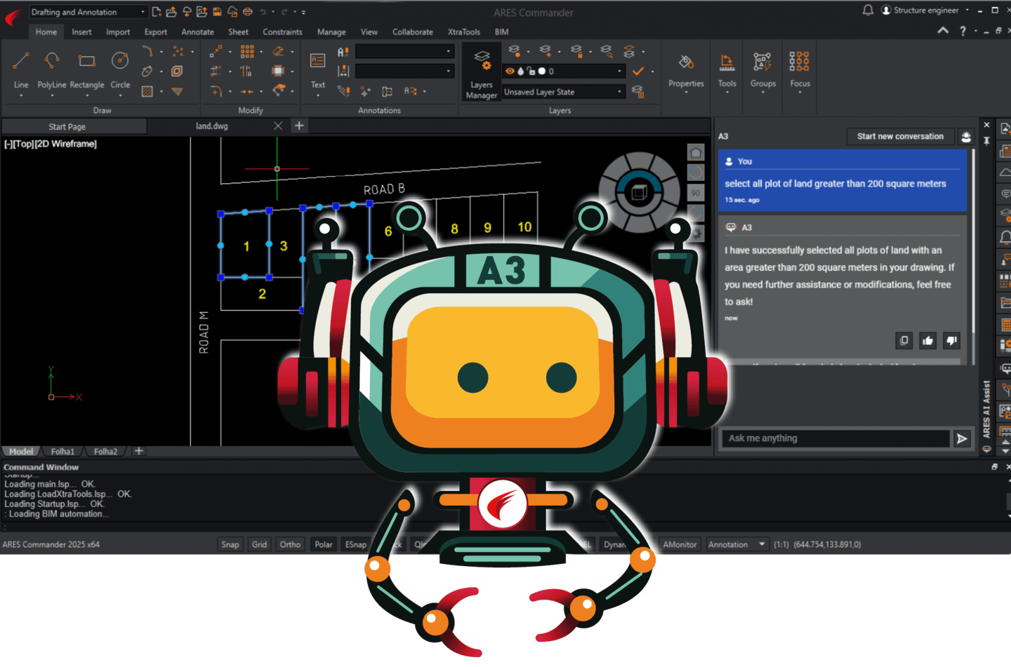
With the latest version of ARES Commander, the CAD assistant feature known as ARES AI Assist (A3)
now allows users to control their drawings using natural language.
Simply describe what you need to do and A3 will carry out your instructions.
AI Assistance for Selections and Modifications
First introduced in the previous version, ARES AI Assist (A3) now enables
users to make selections and modifications using natural language through
its dedicated side palette. Simply enter commands such as Select all lines longer than 5 on the layer Windows to execute actions instantly.
This intuitive approach eliminates complex command sequences, especially for tasks involving multiple adjustments or intricate selection criteria.
Clear, natural language input helps prevent mistakes that often occur when users are entering multiple command-line instructions, leading to more accurate edits and changes.
You can also modify properties effortlessly, via requests like Change the color of all circles to red.
There are already 5 properties that you can modify with AI: the layer, the color, the linetype, the line weight, and the line scale.
For more examples of ways to interact with A3, you can visit www.graebert.com/a3 to download our A3 Cheat Sheet.
AI-Driven Text Tools & MText Improvements
Following the successful introduction of ARES AI Assist (A3), we are expanding the integration of artificial intelligence–powered tools in
ARES Commander.
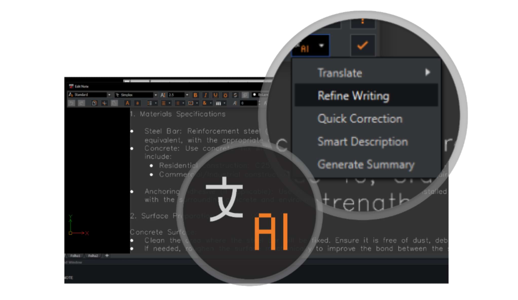
The MText editor has been enhanced with AI-driven tools to translate, refine writing, check spelling, and summarize text. By streamlining common documentation tasks, A3’s new text editing capabilities can save users considerable time, and improve communication within and beyond the CAD environment.
In addition, users can now format text within MText entities into columns, improving readability and layout flexibility. This feature is especially beneficial for complex documentation or design notes, since it helps users organize multi-column text into clearly structured, easy-to-read layouts. It also maximizes the available workspace by efficiently managing text within drawings.

New 2D & 3D CAD Features
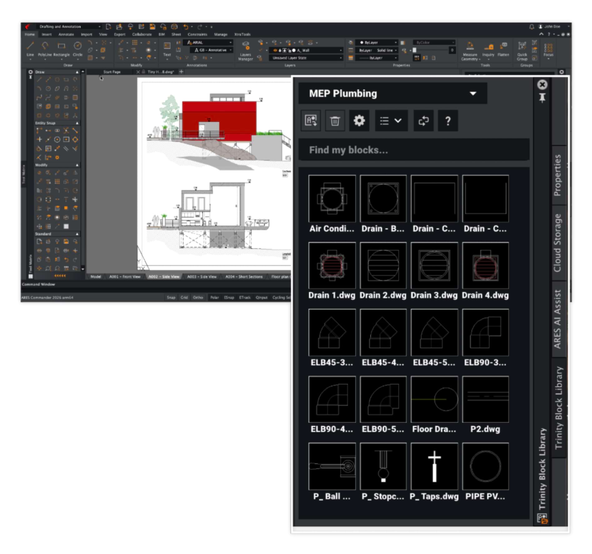
Build more efficient workflows with better tools to work with blocks, dynamic blocks and custom blocks. Thanks to a Trinity Block Library upgrade, you can add and edit blocks in the same UI used for block insertion — making block sharing even easier.
And with full support for multiple visibility states, custom blocks are now functionally equivalent to dynamic blocks created in AutoCAD.
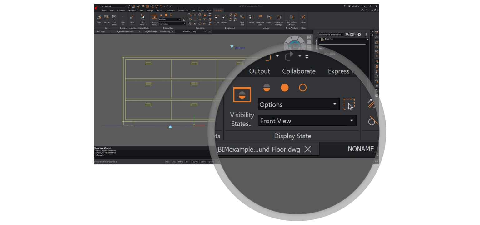
Attach multiple visibility elements to a custom block
Previously in ARES Commander, only one visibility element was
allowed per block.
This constraint has proven to be limiting in certain scenarios. To mitigate this issue, we developed an enhancement for custom blocks, which enables users to attach multiple visibility elements to a single block.
Thanks to this modification to the Edit Block command, users can efficiently control the visibility of individual entities within blocks. This reduces the need to create numerous visibility states, which can be labor-intensive.
Dynamic Blocks & Custom Blocks
ARES Commander and ARES Kudo support both dynamic blocks created with AutoCAD and custom blocks created with ARES Commander.
Watch the following video to see these parametric blocks in action and understand the benefits.
Upgraded Trinity Block Library management and UI
The Trinity Block Library, introduced in previous ARES versions, is a powerful tool that enables users to create custom libraries of blocks stored in the cloud and efficiently share them with colleagues.
In addition to ARES Commander, the Trinity Block Library can also be accessed from ARES Kudo and ARES Touch, making it possible for users to access their collections of blocks on any device.
To expand its capabilities, new features are being added to the Trinity Block Library. These include advanced library management, which supports uploading DWG files containing multiple blocks while enabling individual block insertion. In addition, the library interface has been upgraded, allowing users to add and edit blocks directly from the same UI used for block insertion. These improvements make it easier than ever to organize, access, and customize blocks within the Trinity Block Library.
Included with ARES Trinity
Enhanced Map features performance
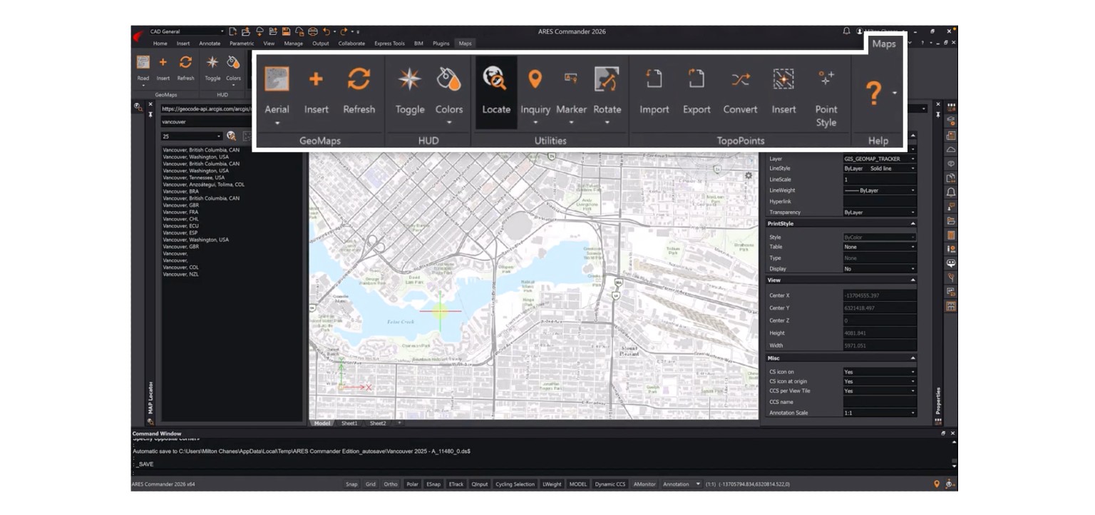
We continue to optimize the Map functionalities in ARES Commander, building on the significant improvements introduced last year.
These included a refactored local caching system for map image service queries and a transition to a tile-based loading system, which minimizes data usage by loading only the visible portions of the map. This year, we have refined key aspects of the process to reduce loading times and make
better use of multiple processor cores. These enhancements result in performance improvements and deliver higher-quality map images, further streamlining the user experience.
Included with Maintenance and/or ARES Trinity

ECW format for efficient image compression
ARES Commander is adding support for the ECW image format.
This format is known for its efficient compression, which makes it ideal for large-scale images such as aerial and satellite photography. ECW files can also include embedded map projection data, enhancing their usefulness in remote sensing and geographic information system (GIS) applications.
3D Rendering of CAD models in Twinmotion
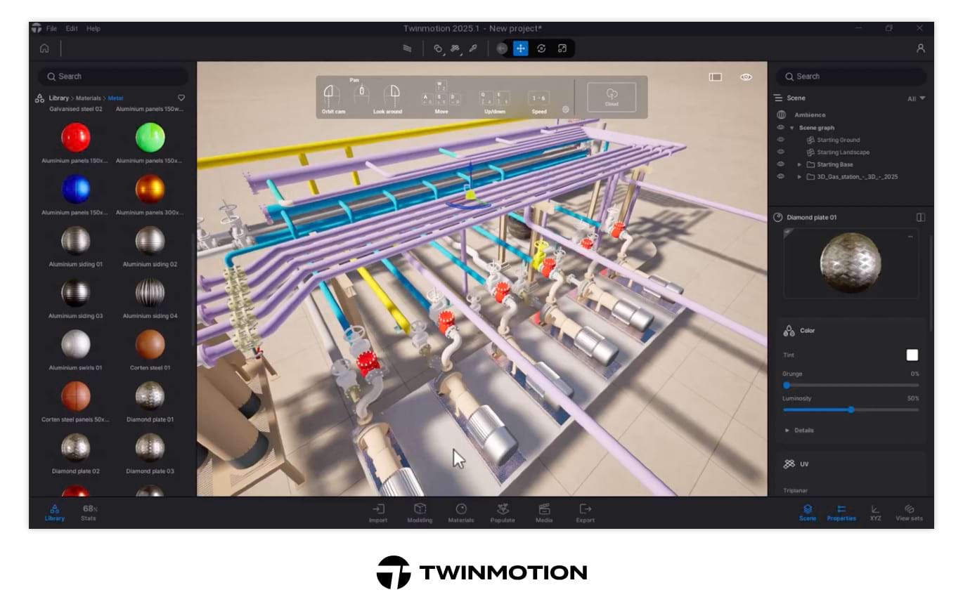
With the EXPORTDATASMITH command, ARES Commander users can now export DWG content to the Datasmith format, which can be opened in such applications as Twinmotion, a real-time rendering tool with extensive options for lighting, materials, and video creation. A free version of Twinmotion is available for certain types of users.
The Datasmith format preserves the DWG file’s geometry, materials, layers, object properties, and hierarchy. Therefore, imported 3D models retain their layer structure, enabling users to navigate layers, inspect blocks, and easily assign materials in Twinmotion.
The Library in Twinmotion provides ready-to-use materials, blocks, vegetation, furniture, human models, and more. Users can apply a material from the Library simply by dragging it onto the desired component, and Twinmotion will automatically update all entities in the same layer.
Once the rendering is complete, users can easily export images or video of the finished project. In the CAD General workspace, the Export Datasmith feature appears in the Export dropdown menu. In the Drafting and Annotation workspace, this feature is also located in the Export tab.
Import STEP models into ARES Commander
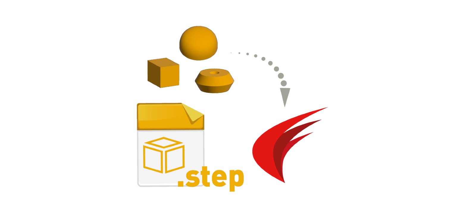
ARES Commander will soon enable users to import 3D models from STEP files, a widely used format for CAD data exchange.
With the introduction of the Import STEP command (IMPORTSTEP), users can easily bring STEP models into their drawings as solid entities. These imported solids can be edited directly within ARES Commander, simplifying workflows and expanding the range of design elements available to users.
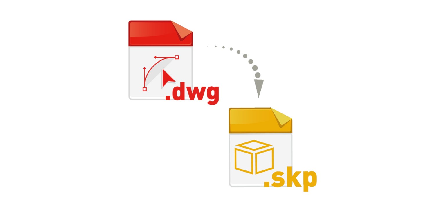
Convert DWG to SketchUp
The ARES Commander 2026 introduces the ability to export drawings directly to the SketchUp format (SKP), using the new Export SketchUp command (EXPORTSKETCHUP).
Depending on the view mode, users can export either a 2D plan view or 3D elements from the current drawing. Elements, including AEC objects, are simplified into line segments for compatibility with SketchUp. This enhancement enables seamless interoperability with SketchUp, which in turn helps design teams to collaborate more effectively, streamline workflows, and improve the overall quality and clarity of project documentation.
CAD Features Performance & Stability Boosts
If CAD software is at the core of your workday, then its performance and stability have an impact on everything you do.
At Graebert, we are devoted to delivering a faster, smoother software experience, so you can focus on what matters.
The numbers tell the story: Our dedication delivers tangible improvements for our users.
This year, we prioritized performance and stability to enhance your workflow.
File Opening Time
Zoom In & Zoom Out
Panning Speed Increase
Switch from Sheet to Model
Switch from Model to Sheet
Improvements have been successively released in recent service packs and in the new version 2026, resulting in:
Users with zero crashes with v.2025 (vs. 91% with v.2024)
Sessions with zero crashes with v.2025 (vs. > 97% with v.2024)
We’re committed to delivering a stable, high-quality experience with each release of ARES Commander. Over the past versions, you may have noticed significant improvements in performance and reliability, reflected in a steady decrease in both crash rates and the number of users affected by crashes. This positive trend is a direct result of focused efforts by our development team.
To prevent regressions and maintain high standards, we’ve implemented new internal filters and automated tests designed to catch potential issues before release. We’ve also optimized our build process to enable faster testing cycles, allowing us to quickly assess stability and performance while investigating each crash thoroughly to pinpoint and resolve the underlying causes.

Support for macOS v15 Sequoia and latest Linux distributions
ARES Commander stands out by offering a single license that works seamlessly across Windows, macOS, and Linux. This flexibility allows users to switch between devices — for example, using the same license on both a Mac laptop and a Windows PC.
ARES Commander 2026 is fully compatible with macOS v15 Sequoia. Two installation packages are available: one for 64-bit Intel processors and another optimized for 64-bit ARM processors (M1, M2, M3, and the latest M4).
ARES Commander 2026 also supports the latest Linux distributions, including Ubuntu 24.04 and Fedora 40.

CAD for BIM in DWG
with ARES Commander 2026Smarter DWG Drawings for BIM Projects
ARES Commander is not a building information modeling (BIM) program; it doesn’t aim to replace Revit or any other BIM software. Instead, it is designed to be the best-in-class CAD solution for working with BIM projects, empowering professionals to bridge the longstanding gap between CAD and BIM — and benefiting users on both sides.
The BIM features in ARES Commander require to stay on Trinity subscription or maintenance
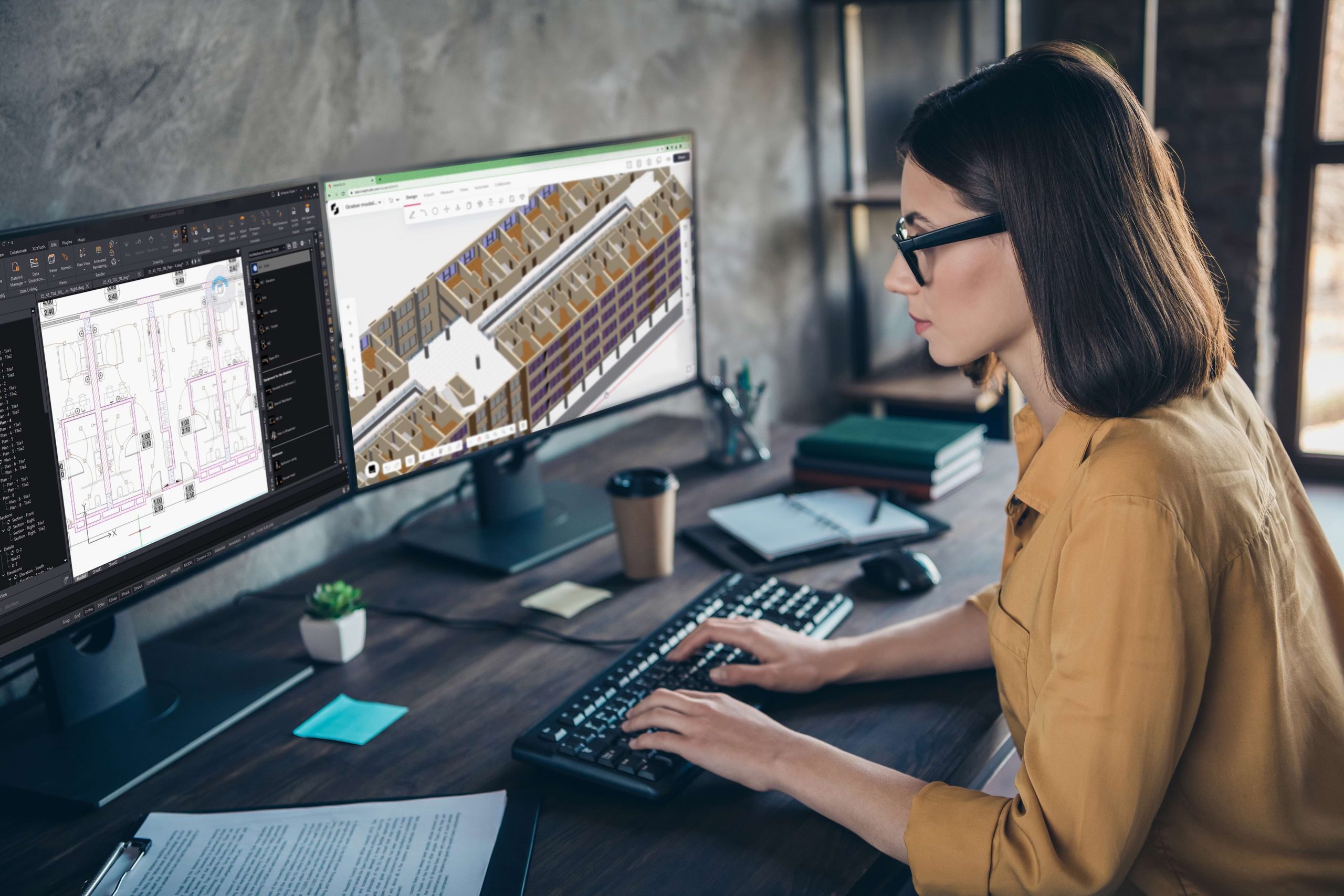
When Information Can’t Flow from BIM to CAD, Work Is Wasted
BIM software applications such as Revit®, ArchiCAD®, and AllPlan® are primarily used for designing buildings in 3D. BIM programs can also be used to generate 2D floorplans, sections, and elevations from the BIM models, but these aren’t sufficient for all purposes; contractors and subcontractors, for example, require more highly detailed 2D execution drawings in DWG format.
Consequently, many professionals create their projects in Building Information Modeling (BIM) software, yet depend on CAD software to create the DWG-format drawings that are essential for project execution.
Unfortunately, a lack of integration often blocks the flow of information between these two types of software. Nearly all DWG-based CAD programs — including AutoCAD — lack the capability to import files in Revit and IFC format and generate drawings from them.
This integration failure means that these CAD users must recreate the existing BIM information in CAD before they can produce the drawings they need — a costly waste of time and effort.
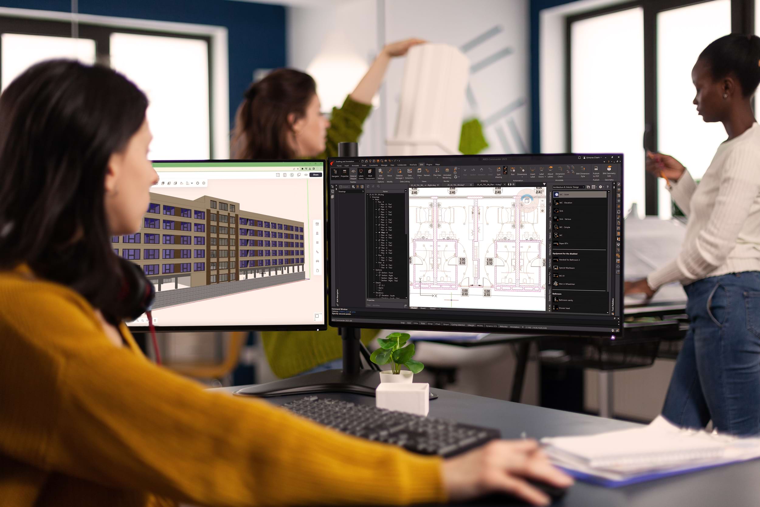
How ARES Commander Overcomes the BIM Barrier
ARES Commander is different from the rest: In addition to a full array of CAD tools, it includes unique BIM-specific features that enable efficient new workflows. Once ARES Commander users import one or more Revit or IFC projects, they can easily access, visualize, and even export their BIM data, supporting better-informed analyses and choices. With the help of BIM filters, users can sort data by type of object, discipline, level, or building, and extract only the information they need. Finally, they can generate smarter DWG drawings that leverage the intelligence contained in those BIM objects.
Automating the drawing creation process
Thanks to ARES Commander’s BIM Drawings Automation features, all those DWG-format drawings — including floorplans, sections, and elevations — can be generated automatically, following a user-customizable script. In contrast to traditional BIM-to-CAD workflows, the user does not recreate information from the BIM model; instead, ARES Commander performs tasks such as adding annotations by reading and extracting detailed properties of the associated BIM entities.
Users can trust ARES Commander to handle the essential — but tedious — chore of drawing creation, while they focus their attention on other tasks.

Keeping BIM drawings up to date effortlessly
BIM models undergo many changes over the course of a project, and to stay current, the associated DWG drawings must be updated — or entirely recreated — repeatedly. When this process is performed manually, it is a terrible waste of resources and a common source of mistakes.
With ARES Commander, in contrast, the DWG drawings can be updated automatically, because they retain their connection to the BIM project they were created from. All the inherited geometry, dimensions, and labels in the drawings will be updated automatically when the BIM model is reloaded. Any CAD geometry that the user has added to the drawing will remain.
Ultimately, the BIM-specific features in ARES Commander — which are growing every year — reduce redundant work and improve collaboration between two worlds that work much better as one.
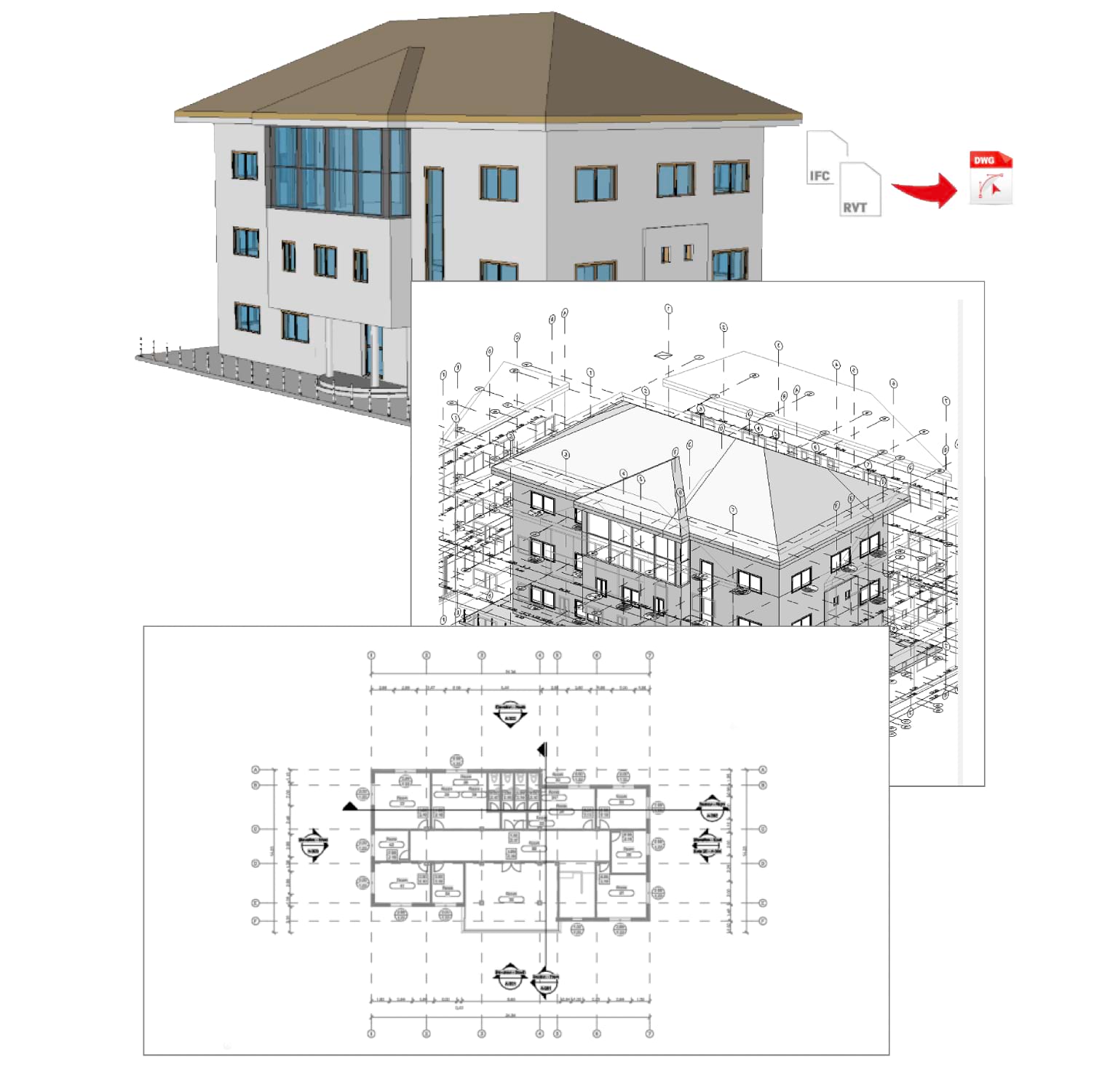
BIM Drawings Automation improvements
Ever since we introduced BIM drawings automation, which facilitates the generation of consistent project documentation through customizable scripts, we have continued to add new functionality.
The new version includes enhancements that help users work more effectively with imported BIM models, clearly represent drawing elements with automatically applied symbols, split drawings into tiles, and more.
Drawings Automation job named “BIM to 2D DWG” will automate successively the following steps:
- 1. Import the Revit or IFC file
- 2. Generate one main DWG drawing with 3D view + multiple 2D DWG drawings by sectioning the BIM model: one floorplan for each level, one elevation for each side of the building and some cross-sections
- 3. Create automatically dimensions on each DWG file by reading the BIM properties of walls, windows and doors
- 4. Create automatic labels for doors, windows and spaces by reading the properties of these BIM objects and placing automatically these labels without overlapping other entities
- 5. Create automatically sheets that are ready to print in the chosen template
Included with Maintenance and/or ARES Trinity
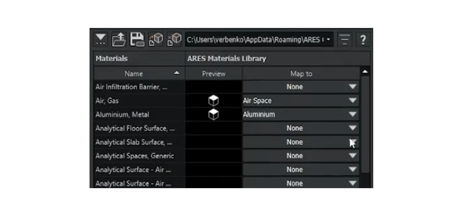
BIM Materials Library Editor
Material hatches play an important role in architectural drawings, ensuring that visual representations align with functional, aesthetic, and technical requirements.
Customizing hatch materials is crucial for accurately reflecting unique project needs, improving readability, adhering to standards, and showcasing a firm’s style. To address this need, ARES Commander will soon have an improved user interface (UI) for customizing the Materials Library. This UI will provide users with greater control over their designs, so they can easily modify colors, hatch patterns, boundary edges, and other properties for both cut elements and projected elements.
Included with Maintenance and/or ARES Trinity
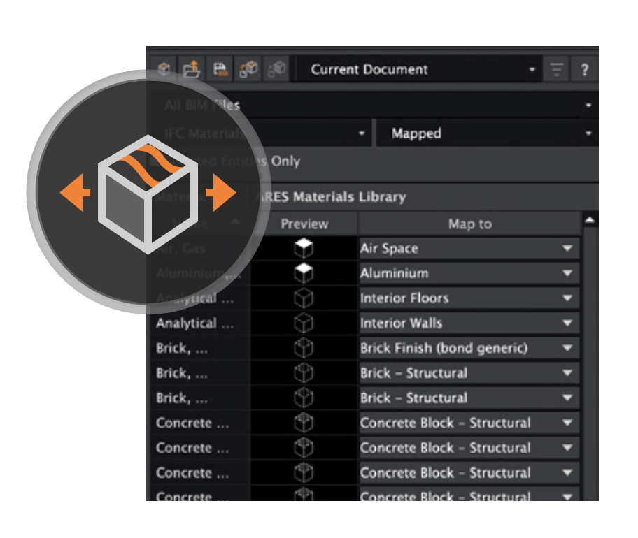
Sharing Material Mapping for BIM Elements
Working in teams requires that everyone uses the same standards. Therefore, we are introducing a way to export and import material mapping for BIM elements.
The BIM Material Mapper allows users to customize BIM material representations in 2D drawings and save configurations as JSON files for easy sharing and reuse. With this feature, you can export company settings for material mapping into a JSON format and share them with your colleagues to ensure consistent output, regardless of who is working on the project. This feature is both a time-saver and a powerful tool for standardizing drawings within an organization. Users can save multiple configuration files, allowing them to create and switch between different drawing styles — whether for architectural plans, structural designs, fire ratings, sales presentations, or any other specific needs.
Included with Maintenance and/or ARES Trinity

Online CAD:
New Features in ARES Kudo
ARES Kudo, the cloud-based version of the ARES CAD software, is a modern CAD application that runs directly inside your Internet browser. Unlike some online programs that are limited to viewing CAD files, ARES Kudo includes a complete set of 300+ features to create, modify, and annotate 2D drawings in DWG — and even visualize 3D files.
The Trinity Collaboration features for ARES Commander, ARES Kudo & ARES Touch require to stay on subscription
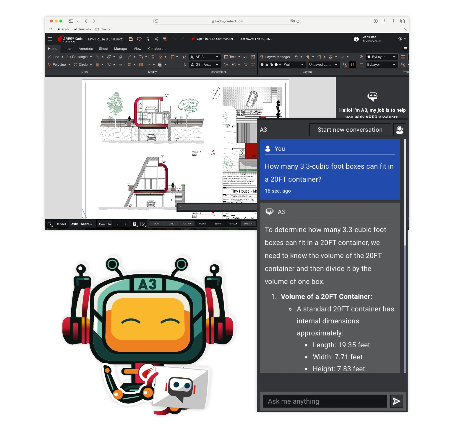
ARES AI Assist (A3) in ARES Kudo
ARES AI Assist (A3) is like having a friendly guide inside ARES Kudo. A3 is an artificial intelligence powered by OpenAI technology.
It is trained to help ARES users in the following ways:
- Explain how to use various features of the software
- Locate features in the user interface
- Customize the user interface
- Provide industry-specific advice
- Perform conversions and calculations
- Translate text into different languages
The A3 pop-up dialog is minimized by default. When users need help with CAD-related tasks, they can simply type at the prompt to interact with A3, which understands many languages. Users who are new to ARES may ask it for help in locating or explaining features. As a result, A3 can be very useful in learning about the Trinity collaboration features, and other features that are unique to ARES products.
A3 can also assist more experienced users by performing calculations, answering technical questions, and translating text, for example. For all types of users, it’s a helpful sidekick that makes learning and using the software much easier and more enjoyable.
Included with ARES Trinity and/or ARES Kudo Professional
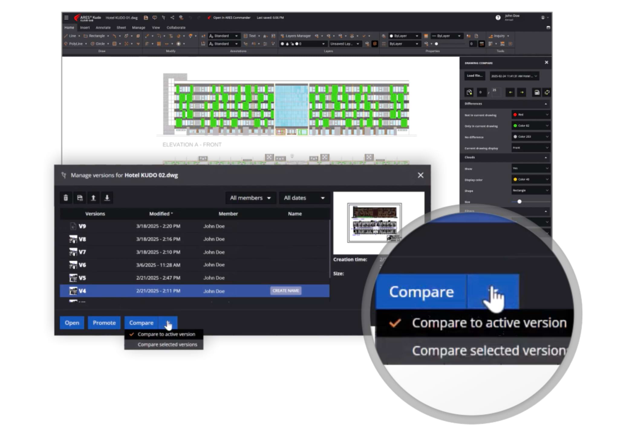
Version Compare & New Version History Manager
The Version History Manager in ARES Kudo has been redesigned with powerful new features.
Users can now compare different versions of a drawing, with changes highlighted in color—for example, comparing the latest update from a colleague with a version saved a week ago. Additionally, users can now name saved versions for better organization, such as “Customer Version” or “Final Version 1”, while continuing to explore new ideas. This makes it easy to track progress, revert changes, and restore previous versions when needed.
Included with ARES Trinity and/or ARES Kudo Professional
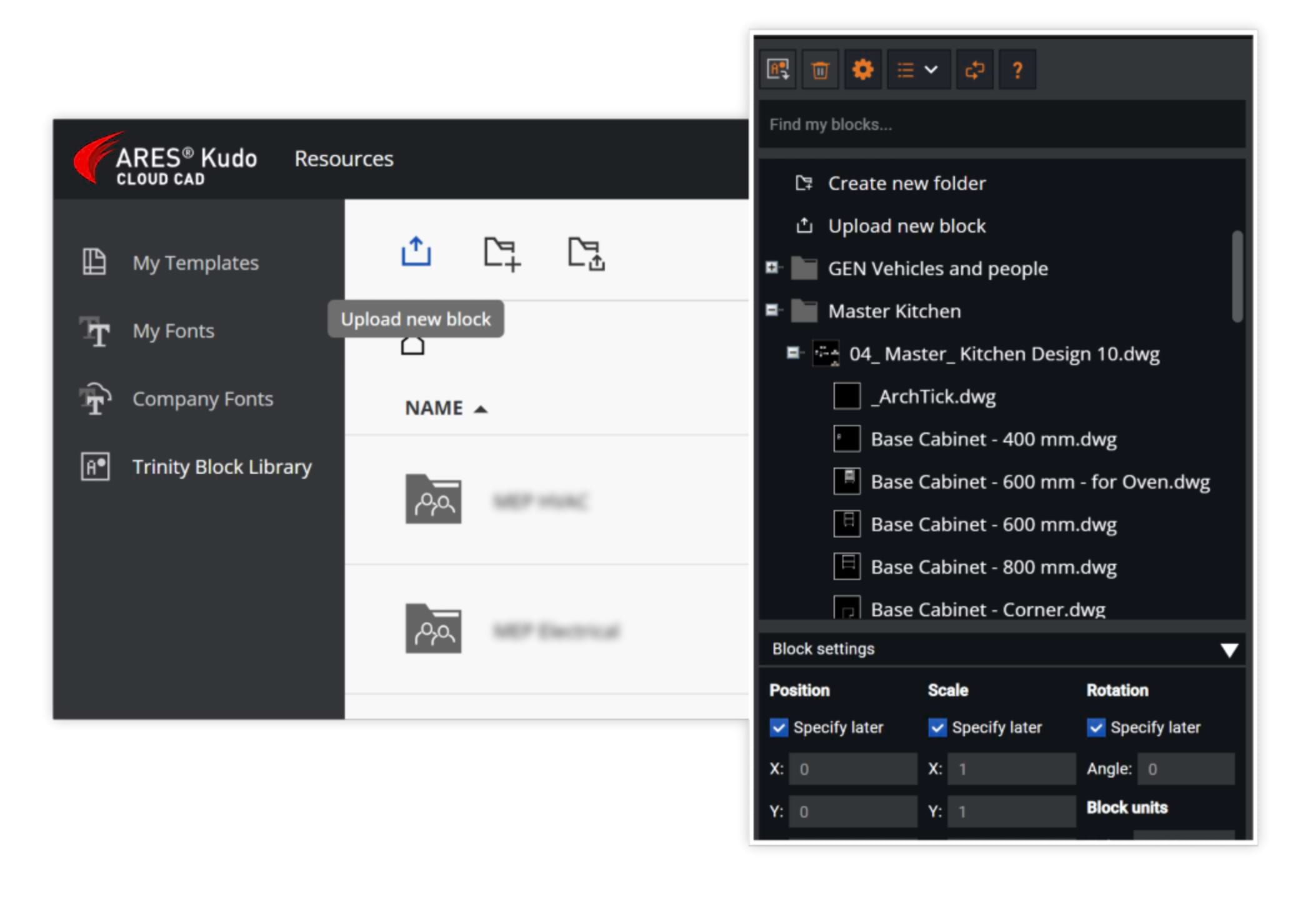
Save Blocks and Share Online Block Libraries
Extract blocks from any DWG file to enrich their library or create new libraries directly from the palette.
Last year, we introduced the Trinity Block Library in ARES Kudo, featuring 450+ ready-to-use blocks. This online library streamlines block creation and sharing, enabling teams to standardize drawings with a common set of blocks. New this year, users can now extract blocks from any DWG file to enrich their library or create new libraries directly from the palette — without leaving the current drawing.
Included with ARES Trinity and/or ARES Kudo Professional
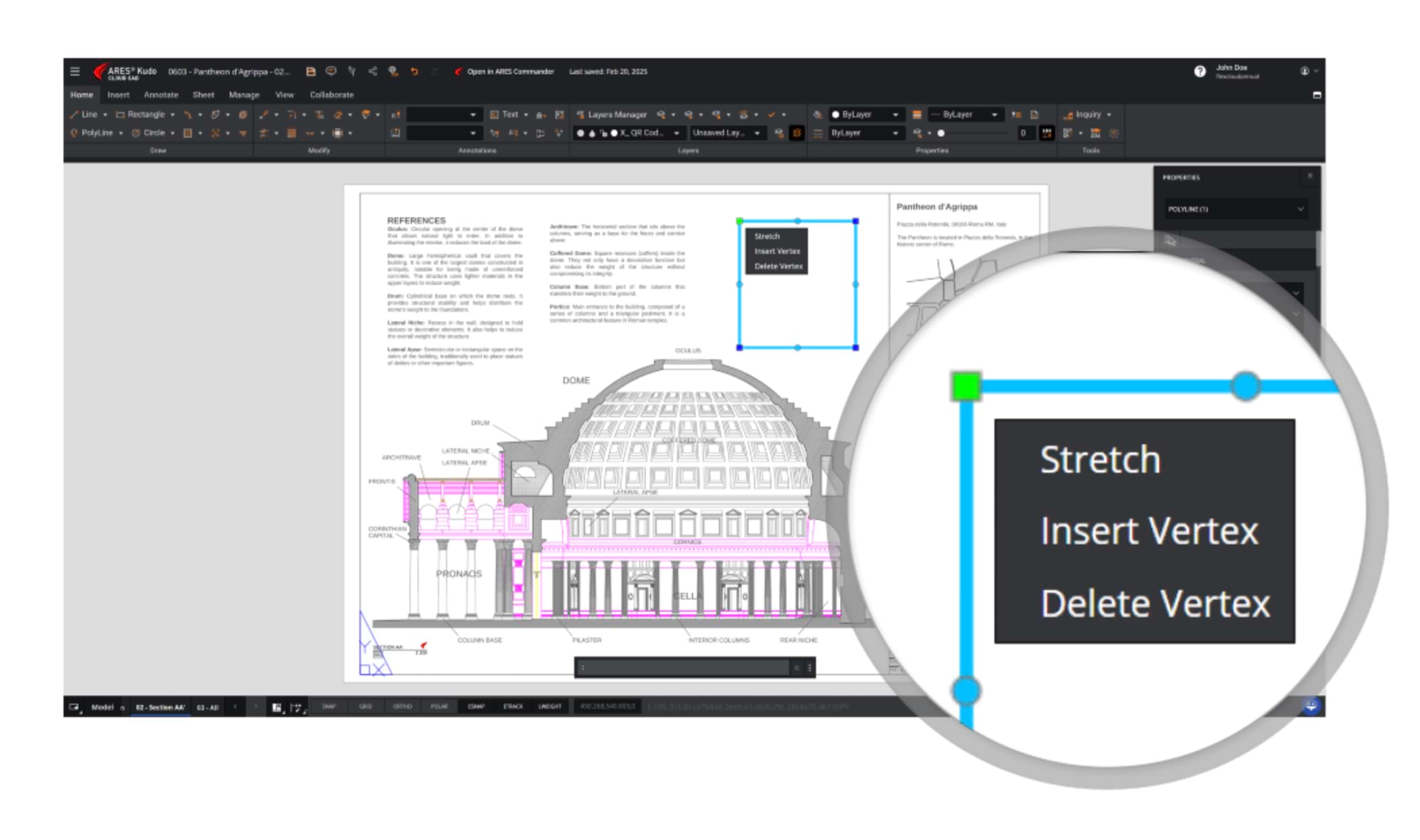
Multifunctional Grips
The Multifunctional Grips feature in ARES Kudo enhances object manipulation by providing context-sensitive grip options for editing entities more efficiently.
Multifunctional Grips are now available for Polylines, providing an intuitive way to modify geometry directly. Users can interact with grips to perform quick edits without needing to activate separate commands.
Included with ARES Trinity and/or ARES Kudo Professional
ARES Online Drawings Automation
and Batch Processing
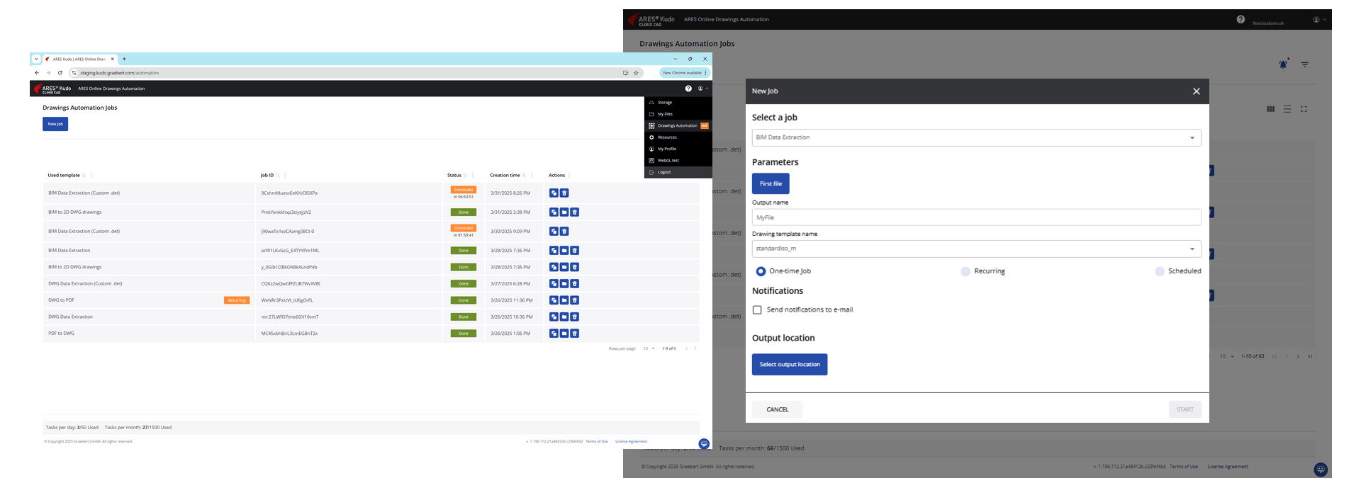
The ARES Command Line Interface (CLI) automation technology has been integrated into ARES Kudo, giving users the ability to offload processing tasks to a server-based version of ARES Commander. It will enable users to trigger jobs directly from the automation UI inside ARES Kudo without opening the editor space, thereby automating workflows that don’t need human intervention.
Included with ARES Trinity and/or ARES Kudo Professional
The Automation service in ARES Kudo will allow users to perform predefined jobs on the files in their cloud storage accounts (Google Drive / Dropbox / Box etc.), and to save the resulting files in cloud storage or download them directly from the Automation page.
Integrating this powerful, flexible technology into ARES Kudo will yield two results:
1. Eliminate the user effort needed to perform repetitive small tasks for a batch of files (when exporting files, for example); and
2. Remove the load on the local system when running a long and demanding task, such as BIM Drawings Automation.
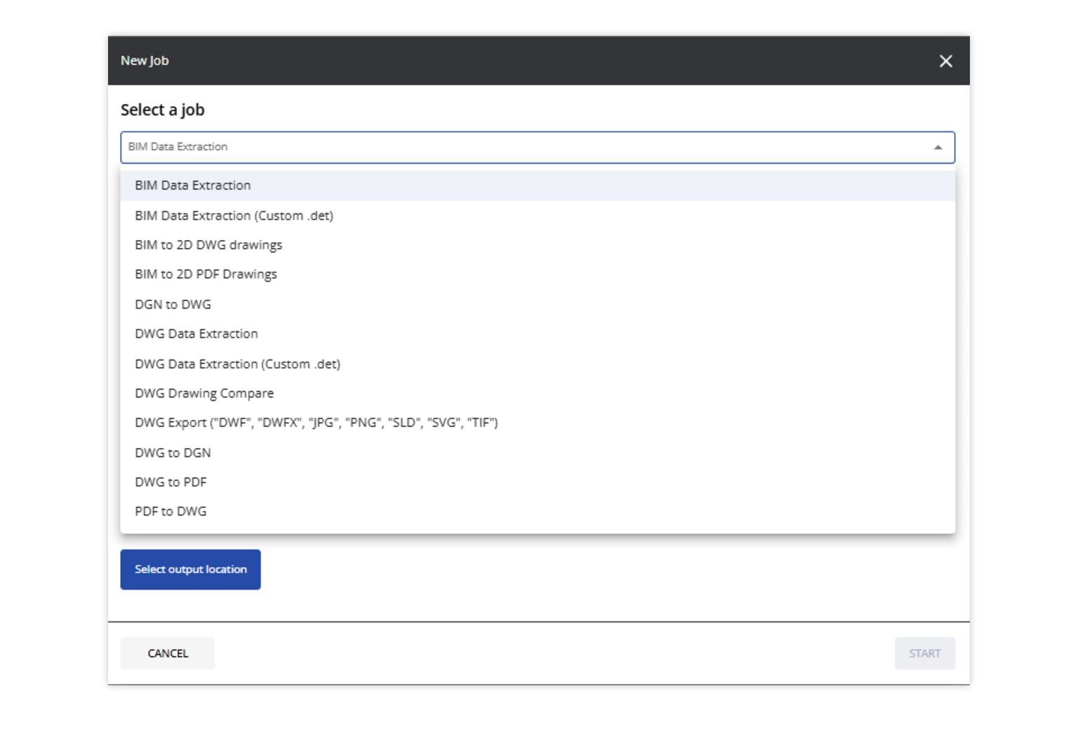
Online BIM Drawings Automation
The new Automation features extend Graebert’s BIM-to-DWG drawings automation to the cloud. ARES Kudo users can now automatically generate 2D floorplans, sections, and elevations from Revit or IFC files, with tasks processed seamlessly on a server-based system.
It is now possible to convert a BIM model to DWG or PDF quickly and easily, using predefined settings. Later, if the BIM model is updated, the documentation can simply be refreshed, instead of recreated from scratch. The automation technology turns formerly laborious, time-consuming chores — such as generating PDFs of BIM models on a nightly basis — into hands-off tasks that require no manual effort.
First, users select the type of job to perform, and then choose the file to automate, whether it’s in RVT or IFC format. Next is selecting a template (ISO or ANSI), which will be applied to all generated drawings. Then there is a choice between executing the automation a single time, or setting up a recurring or scheduled task if the job needs to be performed repeatedly, or on a particular future date. The final step is selecting the cloud storage location where the result will be saved.
Users can always check the status of their automations and verify whether they are completed, are still in progress, or have encountered an error. When a task is complete, the user is notified via email.
Automation saves time, reduces errors, and improves efficiency by performing repetitive tasks consistently and on time.
Included with ARES Trinity and/or ARES Kudo Professional
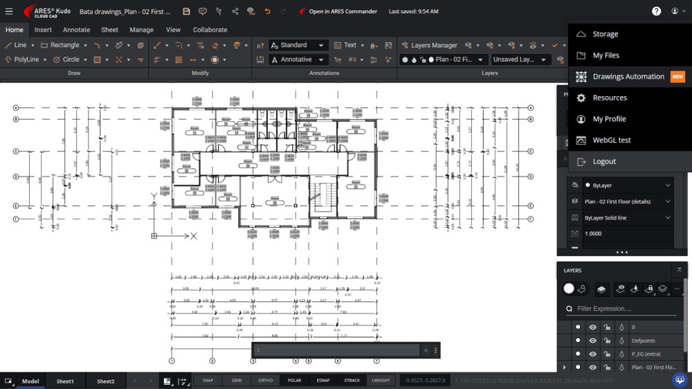
Fig.1 — A DWG floorplan generated from the Revit model with the Automation features and open in ARES Kudo for editing. All the content shown on the screenshot — including the dimensions and labels — were generated automatically from the BIM model and the user can keep editing the drawing leveraging the DWG-based CAD features and ARES Kudo’s AutoCAD-like ribbon interface.

Mobile CAD:
New Features in ARES Touch
ARES Touch is the Mobile version of the ARES CAD software, created specifically for Android smartphone/tablet and iOS iPhone/iPad devices. In addition to a full set of 2D editing features to create, modify, and annotate drawings on the go, it provides visualization of 3D files, and all the collaboration tools offered by our Trinity concept. And its capabilities keep expanding, with new commands for calculating areas and constructing centerlines, and more.
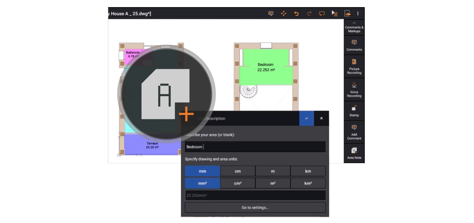
New Area Note Command
Area Note (AREANOTE) is a new command to highlight certain areas inside the drawing — such as rooms or fields, for example — with different standard colors and a transparency effect.
This new annotation tool helps users to calculate areas and represent them with colors and names. Areas can be selected with an internal point or by selecting a contour with points. The area is then filled with a color chosen by the user, with or without transparency. You can find this command in the command list, or in the menu: Annotate > Area Note. The feature will automatically calculate and insert the size of the area (shown in drawing units), and/or label any region with a custom description. The area is created as an anonymous block with block attributes, so you can change the labels, color, and more via the Properties palette.
Included with ARES Trinity and/or ARES Kudo Professional
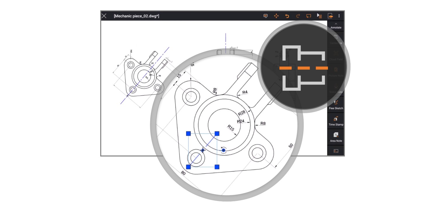
Centerline command
ARES Touch introduces a new annotation centerline. This means that the range of additional annotations is constantly being expanded and the scope of use grows.
Use the CENTERLINE command to construct Centerlines. You can set the extension for Centerlines to exceed the entities which define the contour. Centerlines are created between pairs of Lines, Arcs, and PolyLine segments. Linear contours need not be parallel; the resulting line represents a bisecting line in this case. The two entities can be of different lengths.
Included with ARES Trinity and/or ARES Kudo Professional
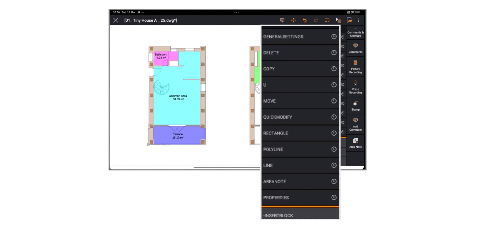
Quick access to recent commands
There is an acute lack of space on mobile devices, which makes it difficult to accommodate the large number of functions included in the software.
Our menu is a container for many commands, some on the top level and some on sub-levels. Now the most recent commands are saved at the top the menu, and you can easily repeat them from the run command list feature.
Included with ARES Trinity and/or ARES Kudo Professional
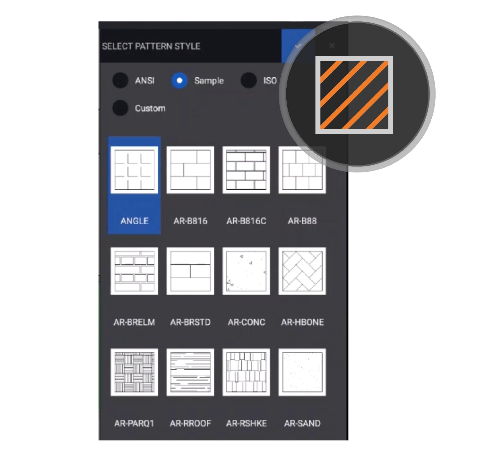
Hatch pattern style preview
Thanks to this new preview functionality, you can see a list of all available hatch pattern styles for every supported pattern type.
What you see is what you get — so now it is easy to choose the right pattern for your needs.
Included with ARES Trinity and/or ARES Kudo Professional
Licensing
We are constantly looking for new ways to improve every aspect of the user experience, including the license activation and management processes. A new version of the Licensing service, which also includes the improvements and bug fixes for the Customer Portal, is typically released every 3 weeks.
Redesigned Customer Portal for Company Admins
The new Graebert Customer Portal simplifies license, user, and device management for ARES administrators.
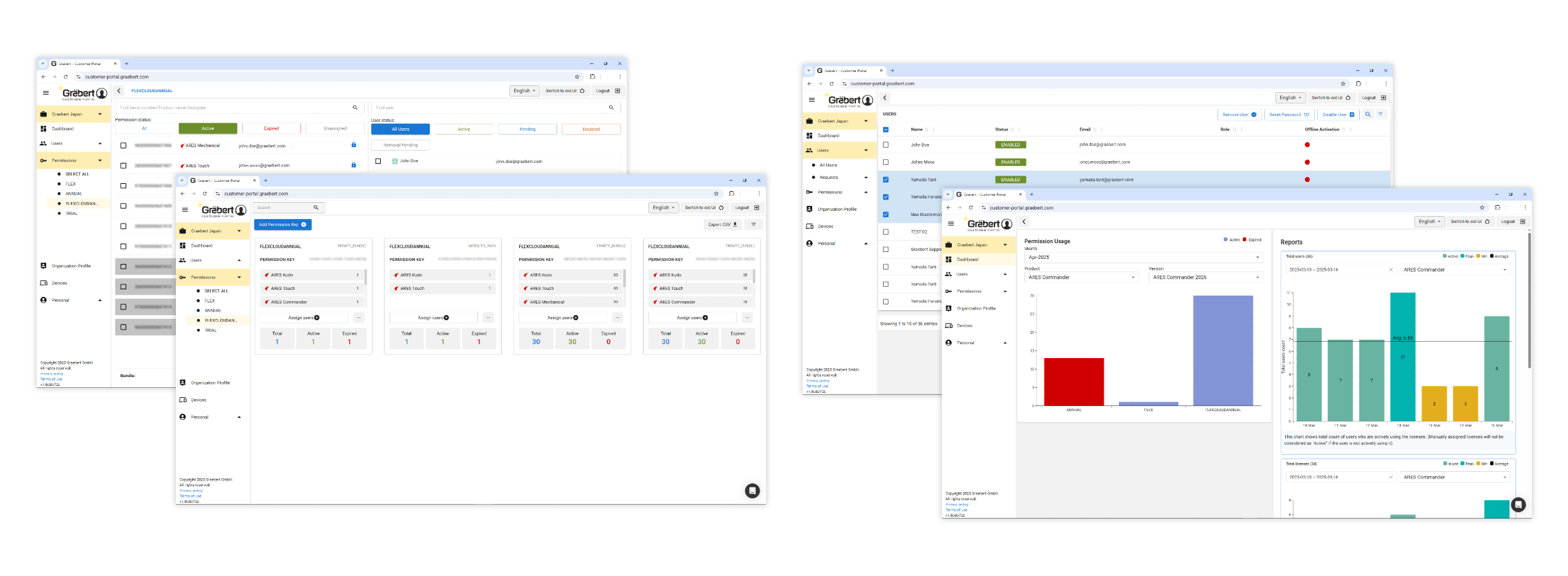
One Central Place to Monitor & Manage Licenses
With an intuitive interface, admins can monitor license activity, manage users, and track permission keys to ensure efficient resource allocation. This streamlined approach helps reduce administrative effort while maintaining full control over license distribution. For Flex Cloud License administrators, the portal offers detailed analytics on license usage and user activity over time.
With comprehensive reporting tools, companies can identify trends, optimize license allocation, and anticipate demand-ensuring licenses are readily available when needed. Admins can access the new experience by navigating to Admin Space > Permissions or Admin Space > Products and clicking the Switch to new UI button.
The updated Admin Space merges the Products and Permissions pages from the previous UI into a unified menu, providing a more cohesive and simplified workflow. Frequently used options are now visually prominent, ensuring quicker and easier access.
An All New Admin Space
The revamped Admin Space introduces several enhancements, including:
- New Layouts: Clean and organized design for improved navigation.
- Advanced Filters: Easily narrow down data for faster decision-making.
- Modal Dialogs: Streamlined interactions for assigning permissions and viewing histories.
- Optimized Workflows: Simplified processes for tasks such as assigning mpermission keys and managing permission history.
Designed to accommodate all sizes of organizations, from small teams to large enterprises, the new Admin Space is fully scalable and adaptable to varied requirements.mIn addition to the visual and functional improvements, the new Admin Space is designed for enhanced performance. It effectively handles data to ensure smooth operations, offering a stable and reliable experience for admins.
Built with efficiency, stability, and scalability in mind, this upgrade provides a seamless, high-performance solution for managing licenses and permissions with ease.

ARES AI Assist (A3) in Customer Portal
ARES AI Assist (A3) has proven to be an invaluable feature within ARES Commander and ARES Kudo, offering users immediate access to the information they seek.
ts ability to highlight commands on the screen in response to user queries and provide targeted assistance has significantly enhanced the user experience. Recognizing its potential to increase productivity, resolve issues quickly, and act as a virtual support agent during critical moments, we are excited to introduce A3 to the Customer Portal. In its initial version, A3 will assist Graebert users by addressing their questions efficiently.
Note: Graebert Licensing comprises the core Licensing server and the web portals for managing users, organizations, and licenses. The Customer Portal can be accessed from the Graebert website or the following address: https://customer-portal.graebert.com/
