How to migrate code from ARX to C++ Tx with ARES Commander’s API – Method # 1
- 21/08/2018
- Posted by: Graebert
- Category: White papers
This article shows you how to port most useful AutoCAD ObjectARX® API features to ARES Commander plugin.
You will learn more about the following topics:
- Creating ARES Commander plugin
-
Porting User Interface features, such as:
• Printing a line to output and requesting user for input
• Porting user-defined commands
- Working with the drawing database
- Porting ObjectARX custom entity
ARES Commander provides API which is almost identical to ObjectARX, but more advanced in some cases, so porting an ObjectARX plugin is a simple and straight-forward task.
Creating ARES Commander Plugin
ARES Commander plugin is a DLL library that exports several common functions and defines a class similar to ObjectARX entry point to handle plugin events. Most of the job is done by predefined macros.
1. Start with DLL project type
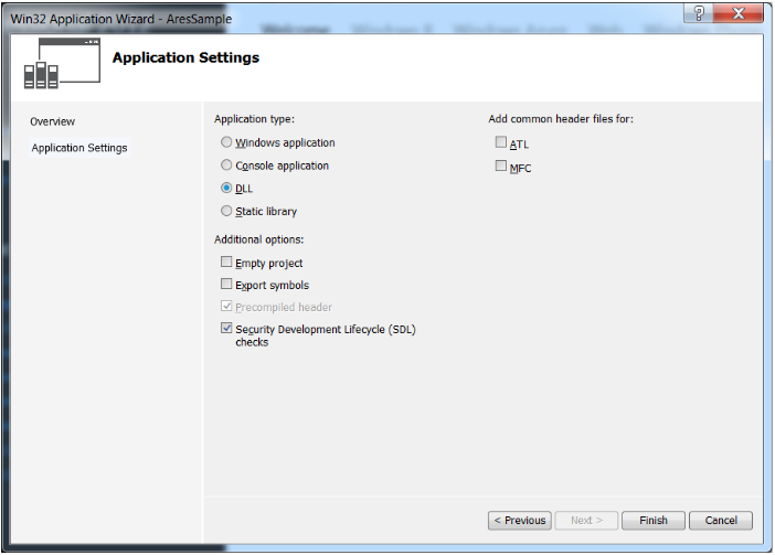
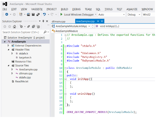
2. Implement ARES module interface
#include “OdaCommon.h”
#include “RxSysRegistry.h”
#include “RxDynamicModule.h”
class AresSampleModule : public OdRxModule
{
public:
void initApp()
{
};
};
ODRX_DEFINE_DYNAMIC_MODULE(AresSampleModule);
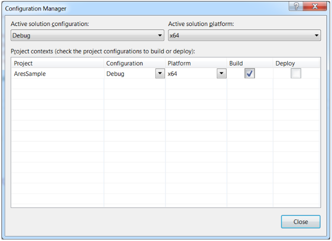
3. Set proper solution platform
In this case, we are using x64 SDK version, so make sure you have set x64 platform.
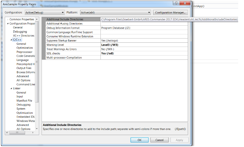
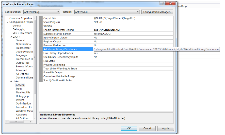
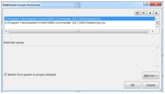
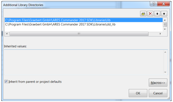
4. Additional include and library directories
In case of AutoCAD, you need libraries from the ObjectARX folder build a plugin. In case of ARES Commander, you need libraries and include files from the ARES SDK folder.
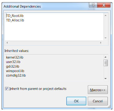
If you try to build the project now, you will get errors, such as
error LNK2019: unresolved external symbol “void __cdecl OdAssert(char const *,char const *,int)”
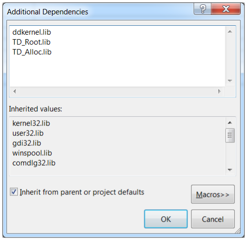
This is because you need to link appropriate libraries that implement ARES Commander plugin API.
Libraries are located on your drive, in \Program Files\Graebert GmbH\ARES Commander 2017 SDK\Libraries\dd_lib
For the beginning, you need the following .lib files:
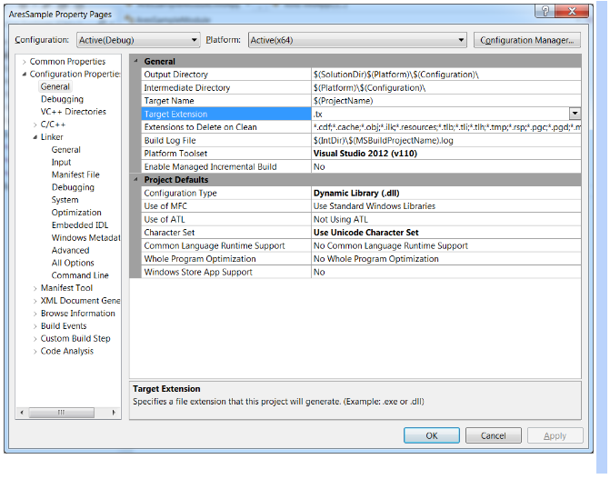
5. Change extension of the output DLL
The shared library containing the subclass of OdRxModule, should be named < application name >.tx.
6. Completing the plugin creation
Now, there are two more steps to make ARES Commander plugin.
Step 1: Define _TOOLKIT_IN_DLL macro
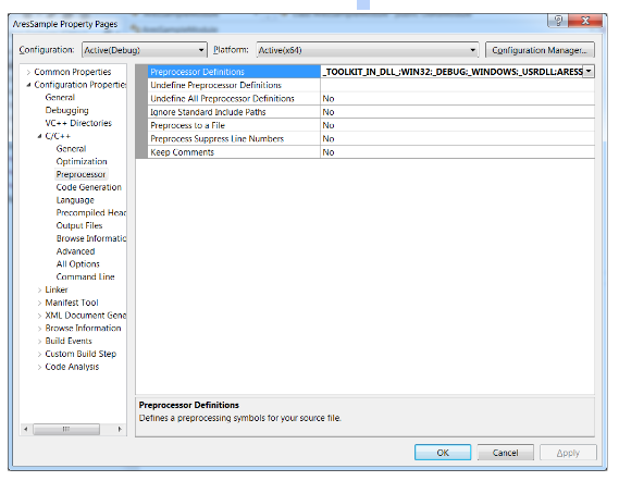
Step 2: Go to C:\Program Files\Graebert GmbH\ARES Commander 2017\BIN and find the files named TD_Db_*.dll;
In our example, it is named TD_Db_4.01_11.dll. You must add the suffix _4.01_11 to your output .dll name to make it load normally.
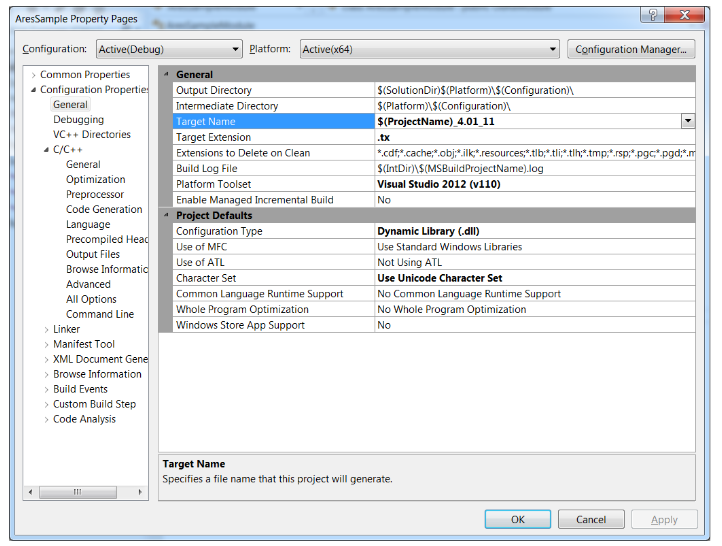
In our example, we have AresSample_4.01_11.tx as result.
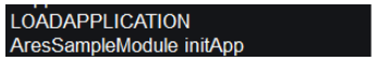
Open ARES Commander and use the APPLOAD command to load your application:
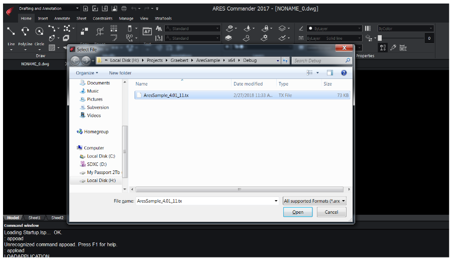
If there are no errors, a confirmation message displays.

Differences and similarities
Porting User Interface features
Porting acutPrintf
Printing a string to output window is a basic AutoCAD user interface feature. It is widely used for logging, tracking plugin call sequence, debugging or interaction with a user. In AutoCAD, this functionality is provided by the acutPrintf function.
Previously, we have created an empty plugin which could be loaded to ARES Commander. It did nothing except calling its entry function.
While developing a plugin, first thing you want is to be able to print something to an output window. In AutoCAD, the acutPrintf function provides this functionality.
On this step, we will add some printing to the plugin and port the code to ARES Commander.
acutPrintf function is replaced by GetFxSystemServices()->WriteLine() in ARES Commander:
#include “FxSystemServices.h”
class AresSampleModule : public OdRxModule
{
public:
void initApp()
{
GetFxSystemServices()->WriteLine( L“AresSampleModule initApp“);
};
void uninitApp()
{
GetFxSystemServices()->WriteLine( L”AresSampleModule uninitApp“);
};
};
Include “FxSystemServices.h” and add ddkernel.lib to additional library dependencies to use GetFxSystemServices:
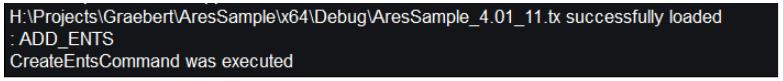
The text message is printed while loading the plugin.
Porting User Defined Commands
User defined commands are one of the basic features of ObjectARX. You can write a function, connect it to an arbitrary command name, type the command name in AutoCAD command line and your function is executed.
void CreateEntities() {…}
acedRegCmds->addCommand(_T(“SAMPLE_COMMANDS“), _T(“SAMPLE_ADD_ENTS“),
_T(“ADD_ENTS”), ACRX_CMD_MODAL, CreateEntities);
If a user types ADD_ENTS, CreateEntities() from the plugin will be called.
ARES Commander provides similar functionality, but the command here is a class instance, not a function pointer. This modern object-oriented approach is more convenient in many cases.
First, we write a command that simply prints a text to the output window, but during the next step a command which creates other entities will be implemented.
Additional headers are needed:
#include “FxCommandContext.h”
#include “FxCommand.h”
ARES command should be derived from CFxCommand base class:
class CreateEntsCommand : public CFxCommand
{
public:
virtual const OdString groupName() const { return(“SAMPLE_COMMANDS”); }
/** Description:
Sets non-localized version of the command name.
*/
virtual const OdString globalName() const { return(“SAMPLE_ADD_ENTS”); }
/** Description:
Sets localized version of the command name.
*/
virtual const OdString localName() const { return(“ADD_ENTS”); }
/** Description:
Executes action.
*/
virtual int Execute( CFxCommandContext* pCmdCtx )
{
GetFxSystemServices()->WriteLine( L“CreateEntsCommand was executed”);
return 0; // normal termination
}
~CreateEntsCommand(void);
protected:
CreateEntsCommand(void);
};
As you can see from the code above, the command has groupName, globalName and localName similar to AutoCAD addCommand function, but in member functions form. They have the same meaning. And finally, instead of a function pointer, CreateEntsCommand has Execute() virtual function which does the job. As any member function, it can use CreateEntsCommand member variables and functions, so we can write clear object-oriented code.
Finally, register this command in the command stack. In AutoCAD command stack is accessible via acedRegCmds macro. In ARES Commander, this functionality is provided by odedRegCmds() function. It returns a pointer to OdEdCommandStack. OdEdCommandStack requires an instance of a command, so we need to create an instance of CreateEntsCommand class and keep it somewhere until it is used by the command stack. In our example we will make the CreateEntsCommand instance a member variable of module class:
class AresSampleModule : public OdRxModule
{
OdStaticRxObject<CreateEntsCommand> m_createCommand;
public:
void initApp()
{
GetFxSystemServices()->WriteLine( L“AresSampleModule initApp”);
OdEdCommandStackPtr pCommandsStack = odedRegCmds();
if ( !pCommandsStack.isNull() )
{
pCommandsStack->addCommand( &m_createCommand );
}
};
void uninitApp()
{
GetFxSystemServices()->WriteLine( L“AresSampleModule uninitApp”);
OdEdCommandStackPtr pCommandsStack = odedRegCmds();
if ( !pCommandsStack.isNull() )
{
pCommandsStack->removeCmd( &m_createCommand );
}
};
};
Now, if you execute the ADD_ENTS command in ARES Commander, the following message appears in the output window:
Working with AutoCAD Basic Entities
As an example, we will use a simple ObjectARX function that creates a circle. This is a command function that is registered as ADD_CIRCLE command:
acedRegCmds->addCommand(_T(“SAMPLE_COMMANDS”), _T(“ADD_CIRCLE”), _T(“ADD_ CIRCLE”), ACRX_CMD_MODAL, createCircle);
void createCircle()
{
AcGePoint3d center;
if (acedGetPoint(NULL, _T(“\nEnter circle center point: “), asDblArray(center)) != RTNORM)
{
acutPrintf(_T(“\nfailed to create a circle”));
return;
}
AcGeVector3d normal(0.0, 0.0, 1.0);
AcDbCircle *pCirc = new AcDbCircle(center, normal, radius);
AcDbObjectId idCircle;
addToModelSpace(idCircle, pCirc);
}
While this function is quite short, it uses a lot of ObjectARX class types and mechanisms.
The following sections describe how to port it step by step to ARES Commander and explain important details.
Ge Classes
First, the function uses “Ge” classes, such as AcGeVector3d and AcGePoint3d. Ge is a subset of AutoCAD (OARX) classes which provide a general representation for 2D and 3D geometric objects such as points, lines, curves and surfaces. Ge classes consist of three main groups by the objects type: planar, curve and surface objects.
These are lightweight classes used for geometric operations, such as finding a closest point, borders or shapes calculations, etc.
Any OARX developer frequently uses these classes, there is no OARX plugin without them. So, how can we port those?
Good news, that ARES SDK provides an exact set of Ge classes, identical to ObjectARX ones! The only difference is in the first two letters of class names. If you use AcGePoint3d then simply change the class name to OdGePoint3d and it will work as OARX class. All operations are the same. Similarily, for the AcGeVector3d ARES class, the corresponding class is OdGeVector3d, etc.
User IO functions
User IO functions are used to request some input from a user: a number, a word, a point, etc. In ObjectARX these functions are: acedGetPoint, acedGetReal, acedGetInt, acedGetKword and others.
ARES SDK provides CFxUserIO class which represents the user input and output and has a similar set of IO functions.
An instance of CFxUserIO is passed to a command Execute() function. For example, the replacement for acedGetInt would be CFxUserIO::GetInt
CFxCommandContext* pCmdCtx;
CFxUserIO* pUserIO = pCmdCtx->GetFxDocument()->GetFxUserIO();
int aResult = 0;
pUserIO-> GetInt(L”Please enter a digit:”, NULL /*default value*/, &aResult);
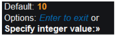
In addition, ARES SDK provides a set of GetPrompt* functions to show a pretty command line prompt instead of a usual AutoCAD-like string. For integer values this function will GetPromptInt:
// this shows pretty prompt string in command line
int defVal = 10;
CFxString prompt = pUserIO->GetPromptInt(L“Specify integer value:”, &defVal);
//this does actual job, getting user input
int aResult = 0;
pUserIO->GetInt(prompt, &defVal, &aResult);
The code above will show the following result in command line:
Db Classes
Db classes, such as AcDbCircle class in the example above, are “database resident” classes. This means that they can be added to a drawing, they have functions to draw on the screen, save & load to a dwg file, they can interact with other objects in the drawing (provide snap and grip points, for example).
Good news is that ARES SDK contains same set of Db classes as ObjectARX and their interface is the same. For AcDbCircle, OdDbCircle will be used in ARES Commander application. Besides, if you have a drawing with AcDbCircle object created with AutoCAD and you load it into ARES Commander, the AcDbCircle object will be loaded as OdDbCircle. All information will be loaded correctly. You can open this object, change it and save to a dwg, and this OdDbCircle object will be loaded as AcDbCircle in AutoCAD!
The only difference is in initialization. ARES Commander uses smart pointer concept instead of OARX raw pointer.
AcDbCircle *pCirc = new AcDbCircle(center, normal, radius);
will be ported as
OdDbCirclePtr pCircle = OdDbCircle::createObject();
pCircle->setCenter( center );
pCircle->setNormal( normal );
pCircle->setRadius( radius );
OdDbCirclePtr is a smart pointer to a Circle object. Besides constructor, all other interface is identical to AutoCAD classes, so it won’t take much efforts to port your OARX plugin.
Append an Entity to Database Modelspace
The last thing which is used in any ObjectARX application is adding entities to database model space. Model space objects are drawn on the screen and are saved or loaded with the .dwg file. ObjectARX approach is the following:
Acad::ErrorStatus addToModelSpace(AcDbObjectId &objId, AcDbEntity* pEntity)
{
AcDbBlockTable *pBlockTable = NULL;
AcDbBlockTableRecord *pModelSpaceRecord = NULL;
acdbHostApplicationServices()->workingDatabase()->getSymbolTable(pBlockTable,
AcDb::kForRead);
pBlockTable->getAt(ACDB_MODEL_SPACE, pModelSpaceRecord, AcDb::kForWrite);
pBlockTable->close();
pModelSpaceRecord->appendAcDbEntity(objId, pEntity);
pEntity->close();
pModelSpaceRecord->close();
return Acad::eOk;
}
The function requests working database (currently open .dwg), gets symbol table from it, gets model space record from the block table and appends newly created entity to the model space.
ARES version does the same thing, but with ARES helper functions the code will be shorter and clearer:
void addToModelSpace(CFxDatabasePtr pDb, OdDbObjectId &objId, OdDbEntityPtr pEntity)
{
OdDbObjectId idModelSpace = pDb->getModelSpaceId();
OdDbBlockTableRecordPtr pModelSpace = idModelSpace.safeOpenObject(OdDb::kForWrite);
objId = pModelSpace->appendOdDbEntity( pEntity );
}
The only difference is what we take database pointer from command context before calling this function. But the rest is similar to ObjectARX.
The Command Ported to ARES Commander
After porting this command to ARES Commander, the command will look like this:
#include “FxSystemServices.h”
#include “FxCommandContext.h”
#include “FxCommand.h”
#include “FxFdtCodes.h”
#include “FxDocument.h”
#include “DbCircle.h”
void addToModelSpace(CFxDatabasePtr pDb, OdDbObjectId &objId, OdDbEntityPtr pEntity)
{
OdDbObjectId idModelSpace = pDb->getModelSpaceId();
OdDbBlockTableRecordPtr pModelSpace = idModelSpace.safeOpenObject(OdDb::kForWrite);
objId = pModelSpace->appendOdDbEntity( pEntity );
}
class CreateEntsCommand : public CFxCommand
{
public:
virtual const OdString groupName() const { return(“SAMPLE_COMMANDS”); }
/** Description:
Sets non-localized version of the command name.
*/
virtual const OdString globalName() const { return(“SAMPLE_ADD_CIRCLE”); }
/** Description:
Sets localized version of the command name.
*/
virtual const OdString localName() const { return(“ADD_CIRCLE”); }
/** Description:
Executes action.
*/
virtual int Execute( CFxCommandContext* pCmdCtx )
{
CFxUserIO* pUserIO = pCmdCtx->GetFxDocument()->GetFxUserIO();
if (!pUserIO) // if there is no active drawing User IO is null. Exit.
return RTERROR;
OdGePoint3d center;
if (pUserIO->GetPoint( L“\nEnter circle center point: “,
NULL, NULL, ¢er) != RTNORM)
{
pUserIO–>Write( L“\nfailed to create a circle” );
return RTERROR;
}
double radius = 0;
if (pUserIO->GetDouble( L“\nEnter circle radius: “, NULL, &radius) != RTNORM)
{
pUserIO->Write( L“\nfailed to create a circle” );
return RTERROR;
}
OdGeVector3d normal(0.0, 0.0, 1.0);
OdDbCirclePtr pCircle = OdDbCircle::createObject();
pCircle->setCenter( center );
pCircle->setNormal( normal );
pCircle->setRadius( radius );
CFxDatabasePtr pDB = pCmdCtx->GetFxDocument()->GetFxDatabase();
OdDbObjectId idCircle;
addToModelSpace(pDB, idCircle, pCircle);
return 0; // normal termination
}
~CreateEntsCommand(void) {}
protected:
CreateEntsCommand(void) {}
};
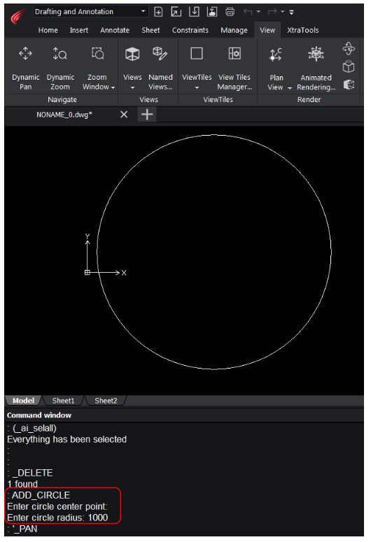
Let’s save this file to a .dwg and open it in Autodesk AutoCAD:
The file opens normally, and we can see the circle which was created in ARES Commander. As you can see, our solution is totally compatible with Autodesk products and .dwg file format.
Working with AutoCAD Database and DWG Format
AutoCAD drawing is an object database that collects various graphical and non-graphical objects. Graphical objects are called entities and derived from AcDbEntity class. Examples of entities are lines, circles, text, etc.
A drawing loaded from a file can contain different information about objects that define the geometry, styles, representations, settings, attached data, and custom objects.
A database serves as the container object for all data loaded from the file. The .dwg file is a persistent representation of an AutoCAD database.
ObjectARX provides AcDbDatabase class which implements operations with the drawing database. Objects derived from AcDbObject ( AcDbEntity ) are “persistent” and can be saved and loaded from .dwg ( “Db” in class name means “database resident” ).
ARES Commader SDK provides identical functionality and identical set of classes to work with .dwg file, so all ARX database operations can be easily ported to ARES Commander. To port ObjectARX code, just replace “Ac” prefix to “Od” and you’ll find the corresponding ARES Commander class.
For example AcDbDatabase class in ObjectARX is replaced with OdDbDatabase in ARES SDK. Entity class like AcDbCircle has corresponding OdDbCircle class in ARES SDK.
What is important here is that ARES SDK classes are fully compatible with ObjectARX classes. You can save an OdDbCircle to a dwg file using OdDbDatabase and load the file in AutoCAD using AcDbDatabase and AcDbCircle. AcDbCircle and OdDbCircle will contain identical information and identical set of fields. The file will be loaded normally and you can continue work with it in AutoCAD. In reverse, if you started the file in AutoCAD you can work with it in ARES Commander.
Saving the Database to a .dwg File
Take a look at createDwg() function which creates an empty database (drawing), adds a couple of circles into it and saves the database to a .dwg file.
void createDwg()
{
AcDbDatabase *pDb = new AcDbDatabase();
AcDbBlockTable *pBtbl = NULL;
pDb->getSymbolTable(pBtbl, AcDb::kForRead);
AcDbBlockTableRecord *pBtblRcd = NULL;
pBtbl->getAt(ACDB_MODEL_SPACE, pBtblRcd, AcDb::kForWrite);
pBtbl->close();
AcDbCircle *pCir1 = new AcDbCircle(AcGePoint3d(1, 1, 1), AcGeVector3d(0, 0, 1), 1.0);
AcDbCircle *pCir2 = new AcDbCircle(AcGePoint3d(4, 4, 4), AcGeVector3d(0, 0, 1), 2.0);
pBtblRcd->appendAcDbEntity(pCir1);
pCir1->close();
pBtblRcd->appendAcDbEntity(pCir2);
pCir2->close();
pBtblRcd->close();
pDb->saveAs(_T(“C:\\Drawings\\test1.dwg”));
delete pDb;
}
We already know how to work with model space and how to create circles in ARES Commander. This time, we will use OdDbDatabase class which replaces AcDbDatabase for ARES Commander plugins.
First, create an empty database:
OdDbDatabasePtr pDb = GetFxSystemServices()->GetHostAppServices()->createDatabase();
Save it to a .dwg file:
pDb->writeFile(L“C:\\Drawings\\test1.dwg”, OdDb::kDwg, OdDb::kDHL_CURRENT);
OdDb::kDwg specifies to write the database as .dwg file and not .dxf;
OdDb::kDHL_CURRENT specifies that the latest .dwg file format version will be used.
Here is the full code:
void createDwg()
{
OdDbDatabasePtr pDb = GetFxSystemServices()->GetHostAppServices()->createDatabase();
OdDbObjectId idModelSpace = pDb->getModelSpaceId();
OdDbBlockTableRecordPtr pModelSpace = idModelSpace.safeOpenObject(OdDb::kForWrite);
OdDbCirclePtr pCircle1 = OdDbCircle::createObject();
pCircle1->setCenter( OdGePoint3d(1,1,1) );
pCircle1->setNormal( OdGeVector3d(0,0,1) );
pCircle1->setRadius( 1.0 );
OdDbCirclePtr pCircle2 = OdDbCircle::createObject();
pCircle2->setCenter( OdGePoint3d(4,4,4) );
pCircle2->setNormal( OdGeVector3d(0,0,1) );
pCircle2->setRadius( 2.0 );
pModelSpace->appendOdDbEntity(pCircle1);
pModelSpace->appendOdDbEntity(pCircle2);
pDb->writeFile(L“C:\\Drawings\\test1.dwg”, OdDb::kDwg, OdDb::kDHL_CURRENT);
}
Note: AcDb (circle) and AcGe (point and vector) classes were simply renamed to OdDb and OdGe. No additional actions required.
Unlike ARX, ARES API does not need to make calls like:
pCir2->close();
pBtblRcd->close();
This is because ARES API uses smart pointers. This simplifies code and makes memory and resource management easier.
Let’s open the test1.dwg in AutoCAD and ARES Commander:
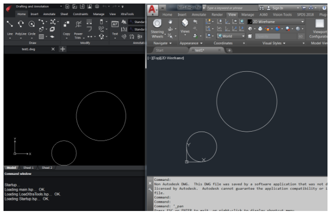
Both applications load and show the file correctly. Which means that ARES API is fully compatible with ObjectARX and AutoCAD.
Reading a .dwg File
Reading a .dwg file is another common case in ARX applications. If you need a database object, you can load it directly from file.
ObjectARX code:
AcDbDatabase *pDb = new AcDbDatabase(Adesk::kFalse);
pDb->readDwgFile( L“C:\\Drawings\\test1.dwg” );
ARES Commander code:
OdDbDatabasePtr pDb = GetFxSystemServices()->GetHostAppServices()->readFile(
L“C:\\Drawings\\test1.dwg”, false , true );
AcDbDatabase and OdDbDatabase have almost identical interface and it is easy to port code which uses AcDbDatabase.
Iterating Model Space
In many cases, the developer wants to iterate through database model space which represents a dictionary of entities in a drawing.
On the previous step, we loaded test1.dwg to a database object. In the next steps, we will demonstrate how model space is iterated in ARX and ARES SDK.
The following function prints class names of objects in model space in AutoCAD:
void readDwg()
{
AcDbDatabase *pDb = new AcDbDatabase(Adesk::kFalse);
if (Acad::eOk != pDb->readDwgFile(_T(“E:\\1\\test1.dwg”)))
return;
AcDbBlockTable *pBlkTbl = NULL;
pDb–>getSymbolTable(pBlkTbl, AcDb::kForRead);
AcDbBlockTableRecord *pBlkTblRcd = NULL;
pBlkTbl->getAt(ACDB_MODEL_SPACE, pBlkTblRcd, AcDb::kForRead);
pBlkTbl->close();
AcDbBlockTableRecordIterator *pBlkTblRcdItr = NULL;
pBlkTblRcd->newIterator(pBlkTblRcdItr);
AcDbEntity *pEnt = NULL;
for (pBlkTblRcdItr->start(); !pBlkTblRcdItr->done(); pBlkTblRcdItr->step())
{
pBlkTblRcdItr->getEntity(pEnt, AcDb::kForRead);
acutPrintf(_T(“classname: %s\n”), (pEnt->isA())->name());
pEnt->close();
}
delete pBlkTblRcdItr;
delete pDb;
}
It reads .dwg file, opens the model space, creates iterator for model space dictionary and goes through each entity in the dictionary.
The main part here is how to iterate a dictionary in ARES SDK. Here is the code:
void readDwg()
{
OdDbDatabasePtr pDb = GetFxSystemServices()->
GetHostAppServices()->readFile( L“C:\\Drawings\\test1.dwg”, false , true );
OdDbObjectId idModelSpace = pDb->getModelSpaceId();
OdDbBlockTableRecordPtr pModelSpace = idModelSpace.safeOpenObject();
OdDbObjectIteratorPtr pIterator = pModelSpace->newIterator();
for(pIterator->start(); !pIterator->done(); pIterator->step())
{
OdDbEntityPtr pEnt = pIterator->entity();
OdString className;
className.format( L“classname: %s”, pEnt->isA()->name() );
GetFxSystemServices()->WriteLine( className );
}
}
While results are the same, ported code is much smaller and easier to read. Smart pointers are used, so there is no need to worry about memory management and calls like close(). AcDbBlockTableRecordIterator was replaced with OdDbObjectIterator which has identical interface.
Database Reactors
As mentioned before, OdDbDatabase provides same API as ARX AcDbDatabase class. For the final demonstration and to make sure that all ARX mechanisms can be easily ported to ARES Commander, we will port a database reactor.
Database reactor in ARX is an instance of a class derived from AcDbDatabaseReactor. AcDbDatabaseReactor has a set of virtual functions, such as objectAppended, objectModified etc. These functions will be triggered once such event takes place in the database.
Usual ARX reactor has the following code sequence:
class CustomDbReactor : public AcDbDatabaseReactor
{
public:
virtual void objectAppended(const AcDbDatabase* dwg, const AcDbObject* dbObj)
{
printEvent(_T(“objectAppended”), dbObj);
}
virtual void objectModified(const AcDbDatabase* dwg, const AcDbObject* dbObj)
{
printEvent(_T(“objectModified”), dbObj);
}
virtual void objectErased(const AcDbDatabase* dwg,
const AcDbObject* dbObj, Adesk::Boolean pErased)
{
printEvent(_T(“objectErased”), dbObj);
}
}
To enable the reactor, you must create an instance and add it to a database:
CustomDbReactor* g_pDbReactor = new CustomDbReactor();
pDb->addReactor(g_pDbReactor);
Again, to porting this to ARES Commander you just need to rename some classes. OdDbDatabaseReactor class implements functionality of AcDbDatabaseReactor for ARES Commander plugins. It has similar interface and the same set of events which can be monitored. Just replace the base class and rename “AcDb” classes to “OdDb”:
#include “DbDatabaseReactor.h”
class CustomDbReactor : public OdDbDatabaseReactor
{
public:
virtual void objectAppended(const OdDbDatabase* dwg, const OdDbObject* dbObj)
{
printEvent(_T(“objectAppended”), dbObj);
}
virtual void objectModified(const OdDbDatabase* dwg, const OdDbObject* dbObj)
{
printEvent(_T(“objectModified”), dbObj);
}
virtual void objectErased(const OdDbDatabase* dwg, const OdDbObject* dbObj, bool pErased = true)
{
printEvent(_T(“objectErased”), dbObj);
}
};
// CustomDbReactor is derived from OdRxObject which has addRef/release interface for library’s smart pointers
// by default, these are pure virtual methods and should be implemented in derived classes
// OdStaticRxObject object template adds empty implementation for these methods, meaning that the class doesn’t need memory management
OdStaticRxObject<CustomDbReactor> dbReactor;
// Register the reactor object with the database instance. Since this, CustomDbReactor’s
// callbacks will be called upon specified events
pDb->addReactor(&dbReactor);
A reactor can be ported in just a few clicks.
Porting a Custom Entity
Implementing custom entities is the main feature of ObjectARX® API. Standard AutoCAD provides only basic entities, such as lines, circles, polygons, etc. But in most cases, you can achieve better design and productivity using entities specific to the area on which you are working. For example, if you draw a house, it is better to manipulate walls and doors instead of simple lines. Similarily, if your drawing is related to furniture, it is better to use a cupboard, a table and similar entities.
Custom objects mechanism provides necessary API for writing your own objects. You can implement load and save functions to save it to a .dwg file, drawing functions to draw it as needed, snap and grip points functions to interact with other entities, and so on.
Most of ObjectARX projects provide their own custom objects.
ObjectARX custom object can be easily ported to ARES Commander, as ARES SDK provides all base classes and APIs similar to AutoCAD. And what is important, such ported objects can be loaded from .dwg files which were previously saved with AutoCAD.
In this example, we are porting a Pipe custom object, which represents a set of connected pipes. The following paragraphs provide a step by step explanation of custom object basics.
Defining a Custom Entity
If a custom object has graphical representation, AcDbEntity is usually used as base class. Below you can see the simplest definition of a custom object. It can only be created and added to model space. It cannot save itself or draw on the screen.
// header file
class PipeEntity : public AcDbEntity
{
public:
ACRX_DECLARE_MEMBERS(PipeEntity);
PipeEntity() {};
virtual ~PipeEntity() {};
};
//cpp file
ACRX_DXF_DEFINE_MEMBERS(PipeEntity, AcDbEntity,
AcDb::kDHL_CURRENT, AcDb::kMReleaseCurrent,
AcDbProxyEntity::kAllAllowedBits, ASDKPIPE,
“ARES SAMPLE”);
Macros here define basic entity functions, such as isA(), desc(), cast() and rxInit(). These are ObjectARX RTTI support.
ARES SDK provides OdDbEntity class which can be used as a base class for custom entity and provides similar interface with AcDbEntity.
The following code sequence describes the port to ARES Commander:
#include “RxObject.h”
#include “DbProxyEntity.h”
class PipeEntity : public OdDbEntity
{
public:
ODRX_DECLARE_MEMBERS(PipeEntity);
PipeEntity() {};
virtual ~PipeEntity() {};
};
ODRX_DXF_DEFINE_MEMBERS(PipeEntity, // class name
OdDbEntity, // parent class name
DBOBJECT_CONSTR, // creation macro
OdDb::kDHL_CURRENT, // dwg version
OdDb::kMReleaseCurrent, // maintenance release version
OdDbProxyEntity::kTransformAllowed |
OdDbProxyEntity::kColorChangeAllowed |
OdDbProxyEntity::kLayerChangeAllowed, // proxy flags
ASDKPIPE, // DXF name, an arbitrary string that will be used in dxf save\load operations
ARES SAMPLE) // Application name (arbitrary string)
ACRX_ macro was changed to ODRX_; AcDb* classes were changed to OdDb* classes. Apart of that, no changes were made.
Registering a Custom Entity
Second step is to register our custom class in AutoCAD or ARES Commander global class list. This is used for SDK’s internal mechanisms.
Registration is usually called from plugin’s entry point. The following sequence illustrates AutoCAD code.
AcRx::AppRetCode acrxEntryPoint(AcRx::AppMsgCode msg, void* appId)
{
switch (msg) {
case AcRx::kInitAppMsg:
PipeEntity::rxInit(changeAppNameCallback);
acrxBuildClassHierarchy();
break;
case AcRx::kUnloadAppMsg:
deleteAcRxClass(PipeEntity::desc());
acrxBuildClassHierarchy();
break;
}
return AcRx::kRetOK;
}
ARES Commander version looks similar, but requires less coding:
class AresSampleModule : public OdRxModule
{
public:
void initApp()
{
PipeEntity::rxInit();
};
void uninitApp()
{
PipeEntity::rxUninit();
};
};
dwgInFields / dwgOutFields
Next, custom objects need a way of save or load its state to a persistent storage. There are two possibilities:
-
- Saving an object to a .dwg file
- Saving it to a dxf.
The following section describes the .dwg case.
ObjectARX provides AcDbDwgFiler class which allows to write data to a stream. AcDbDwgFiler has a set of functions, such as writeInt32, writePoint2d, etc. to save and load basic ARX types.
Imagine that pipe object has internal data: vector of nodes in which pipe changes direction and a vector of widths – diameter of each segment of a pipe:
class PipeEntity : public AcDbEntity
{
std::vector<AcGePoint2d> m_nodes;
std::vector<double> m_widths;
public:
ACRX_DECLARE_MEMBERS(PipeEntity);
PipeEntity() {};
virtual ~PipeEntity() {};
virtual Acad::ErrorStatus dwgInFields(AcDbDwgFiler* filer)
{
assertWriteEnabled();
m_nodes.clear();
m_widths.clear();
Adesk::Int32 nodesCount = 0;
filer->readInt32(&nodesCount);
for (int i = 0; i < nodesCount; i++)
{
AcGePoint2d ptNode;
filer->readPoint2d(&ptNode);
m_nodes.push_back(ptNode);
}
Adesk::Int32 widthsCount = 0;
filer->readInt32(&widthsCount);
for (int i = 0; i < widthsCount; i++)
{double w = 0;
filer->readDouble(&w);
m_widths.push_back(w);
}
return filer->filerStatus();
}
virtual Acad::ErrorStatus dwgOutFields(AcDbDwgFiler* filer) cons
{
assertReadEnabled();
filer->writeInt32(m_nodes.size());
for (int i = 0; i < m_nodes.size(); i++)
filer->writePoint2d(m_nodes[i]);
filer->writeInt32(m_widths.size());
for (int i = 0; i < m_widths.size(); i++)
filer->writeDouble(m_widths[i]);
return filer->filerStatus();
}
};
Porting dwgIn and dwgOut is straightforward as well. ARES SDK provides OdDbDwgFiler class, which replaces AcDbDwgFiler. It has identical interface but uses Od* classes instead of Ac*. Od* classes saved to the Dwg filer are binary compatible to Ac* classes, so AcGePoin2d saved in AutoCAD can be loaded as OdGepoint2d in ARES Commander:
#include “DbFiler.h”
class PipeEntity : public OdDbEntity
{
std::vector<OdGePoint2d> m_nodes;
std::vector<double> m_widths;
public:
ODRX_DECLARE_MEMBERS(PipeEntity);
PipeEntity() {};
virtual ~PipeEntity() {};
virtual OdResult dwgInFields(OdDbDwgFiler* filer)
{
assertWriteEnabled();
m_nodes.clear();
m_widths.clear();
OdInt32 nodesCount = filer->rdInt32();
for (int i = 0; i < nodesCount; i++)
{
OdGePoint2d ptNode = filer->rdPoint2d();
m_nodes.push_back(ptNode);
}
OdInt32 widthsCount = filer->rdInt32();
for (int i = 0; i < widthsCount; i++)
{
double w = filer->rdDouble();
m_widths.push_back(w);
}
return filer->filerStatus();
}
virtual void dwgOutFields(OdDbDwgFiler* filer) const
{
assertReadEnabled();
filer->wrInt32(m_nodes.size());
for (int i = 0; i < m_nodes.size(); i++)
filer->wrPoint2d(m_nodes[i]);
filer->wrInt32(m_widths.size());
for (int i = 0; i < m_widths.size(); i++)
filer->wrDouble(m_widths[i]);
}
};
Changes are small. Functions such as readInt32 and writeInt32 were replaced with rdInt32 \ wrInt32. dwgOutFields returns void. AcDbDwgFiler was replaced to OdDbDwgFiler. Save and load functions can be ported in almost no time.
worldDraw
Besides save & load, we are interested in rendering the pipe. Custom objects can override AcDbEntity subWorldDraw function and provide its own rendering code. PipeEntity draws two lines for each pipe segment. Distance between lines is equal to pipe segment width.
What interests us most is general ARX mechanisms used in worldDraw and how can they be ported to ARES Commander.
In AutoCAD, the drawing function will have the following code sequence:
AcGePoint3d to3D(const AcGePoint2d& pt)
{
return AcGePoint3d(pt.x, pt.y, 0);
}
Adesk::Boolean PipeObject::subWorldDraw(AcGiWorldDraw* wd)
{
assertReadEnabled();
AcGeVector3d normal(0, 0, 1);
AcGePoint3d segmentPoints[2];
for (int i = 0; i < m_nodes.size() – 2; i++)
{
wd->subEntityTraits().setSelectionMarker(i + 1);
segmentPoints[0] = to3D(m_nodes[i]);
segmentPoints[1] = to3D(m_nodes[i+1]);
wd->geometry().polyline(2, segmentPoints, &normal);
}
return Adesk::kTrue; // Don’t call viewportDraw()
}
What is important here is that subWorldDraw() is called each time AutoCAD renders this entity and AcGiWorldDraw interface it provides. Custom entity draws itself using AcGiWorldGeometry pointer returned by wd->geometry() call.
ARES SDK does the same thing. subWorldDraw is called each time ARES Commander renders the entity and a pointer to OdGiWorldDraw is provided. Interfaces are similar, geometry () call returns OdGiWorldGeometry reference which replaces AcGiWorldGeometry. Just by replacing Ac* to Od* we can port the whole entity rendering:
OdGePoint3d to3D(const OdGePoint2d& pt)
{
return OdGePoint3d(pt.x, pt.y, 0);
}
bool subWorldDraw(OdGiWorldDraw* wd)
{
assertReadEnabled();
OdGePoint3d segmentPoints[2];
OdGeVector3d normal(0, 0, 1);
for (int i = 0; i < m_nodes.size() – 2; i++)
{
wd->subEntityTraits().setSelectionMarker(i + 1);
segmentPoints[0] = to3D(m_nodes[i]);
segmentPoints[1] = to3D(m_nodes[i+1]);
wd->geometry().polyline(2, segmentPoints, &normal);
}
return true; // Don’t call viewportDraw()
}
Putting all together
The full source code of the custom entity ported to ARES Commander is the following:
OdGePoint3d to3D(const OdGePoint2d& pt)
{
return OdGePoint3d(pt.x, pt.y, 0);
}
class PipeEntity : public OdDbEntity
{
std::vector<OdGePoint2d> m_nodes;
std::vector<double> m_widths;
public:
ODRX_DECLARE_MEMBERS(PipeEntity);
PipeEntity() {};
virtual ~PipeEntity() {};
virtual OdResult dwgInFields(OdDbDwgFiler* filer)
{
assertWriteEnabled();
m_nodes.clear();
m_widths.clear();
OdInt32 nodesCount = filer->rdInt32();
for (int i = 0; i < nodesCount; i++)
{
OdGePoint2d ptNode = filer->rdPoint2d();
m_nodes.push_back(ptNode);
}
OdInt32 widthsCount = filer->rdInt32();
for (int i = 0; i < widthsCount; i++)
{
double w = filer–>rdDouble();
m_widths.push_back(w);
}
return filer->filerStatus();
}
virtual void dwgOutFields(OdDbDwgFiler* filer) const
{
assertReadEnabled();
filer->wrInt32(m_nodes.size());
for (int i = 0; i < m_nodes.size(); i++)
filer->wrPoint2d(m_nodes[i]);
filer->wrInt32(m_widths.size());
for (int i = 0; i < m_widths.size(); i++)
filer->wrDouble(m_widths[i]);
}
bool subWorldDraw(OdGiWorldDraw* wd)
{
assertReadEnabled();
OdGePoint3d segmentPoints[2];
OdGeVector3d normal(0, 0, 1);
for (int i = 0; i < m_nodes.size()-2; i++)
{
wd->subEntityTraits().setSelectionMarker(i + 1);
segmentPoints[0] = to3D(m_nodes[i]);
segmentPoints[1] = to3D(m_nodes[i+1]);
wd->geometry().polyline(2, segmentPoints, &normal);
}
return true; // Don’t call viewportDraw()
}
};
ODRX_DXF_DEFINE_MEMBERS(PipeEntity, // class name
OdDbEntity, // parent class name
DBOBJECT_CONSTR, // creation macro
OdDb::kDHL_CURRENT, // dwg version
OdDb::kMReleaseCurrent, // maintenance release version
OdDbProxyEntity::kTransformAllowed |
OdDbProxyEntity::kColorChangeAllowed |
OdDbProxyEntity::kLayerChangeAllowed, // proxy flags
ASDKPIPE, // DXF name
ARES SAMPLE) // Application name
class AresSampleModule : public OdRxModule
{
public:
void initApp()
{
PipeEntity::rxInit();
};
void uninitApp()
{
PipeEntity::rxUninit();
};
};
ODRX_DEFINE_DYNAMIC_MODULE(AresSampleModule);
This is an example of custom entity which can load and save its state to .dwg file and draw itself on the screen.
The best thing about it is the fact that the ARES Commander entity is fully compatible with its AutoCAD version. A user can create such an entity in AutoCAD using OARX code, save it to .dwg and load it in ARES Commander using ARES Commander version.
Conclusion
This article demonstrated porting of basic AutoCAD API to ARES Commander. The most important thing about ARES API is that it is compatible and almost identical to AutoCAD API. This allows smooth and easy migration AutoCAD plugins and users to ARES Commander, as well as using ARES Commander along with AutoCAD if necessary.
Companies that would like to move to ARES Commander can do it gradually, porting their AutoCAD applications one by one. There is no need to rush and port all at once. All drawings created with AutoCAD can be used in ARES Commander without migrating huge .dwg libraries and archives.
Easy migration, binary compatibility with AutoCAD and reasonable pricing in comparison to AutoCAD make ARES Commander a perfect candidate as an AutoCAD alternative.
Download this article as a white paper PDF here.
Available Now: New FxARX API Enables Compatibility With ObjectARX